SIMPLIS Parts
SIMPLIS Parts
|
The Digital Lookup Table models combinatorial logic defined with a truth table. The truth table maps logical combinations of input states to output states. A default output state determines the output if the input state is not defined in the table.
The digital lookup table is one of the most powerful and, at the same time, one of the most overlooked of the SIMPLIS digital devices. Using a digital lookup table, you can easily implement, test, and revise extremely complex logic, all without changing the schematic view of the design.
This lookup table requires that all input signal combinations be defined for each state. If you need to define one or more input states with a don't care input, see Digital Lookup Table with Don't Care Input Definitions.
In this Topic Hide
Model Name: |
Digital Lookup Table |
|
Simulator: |
|
This device is compatible with the SIMPLIS simulator. |
Parts Selector |
Digital Functions | Functions |
|
Symbol Library: |
None - the symbol is automatically generated when placed or edited. |
|
Model File: |
None - the device model is generated before simulation. |
|
Subcircuit Name: |
|
|
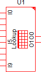
Symbol: |
|
|
Multiple Selections: |
Only one device at a time can be edited. |
|
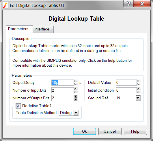
To configure the digital lookup table, follow these steps:
| Label | Parameter Description |
Output Delay |
Delay from when the input state changes until the output changes |
Number of Input Bits |
Number of input bits for the digital lookup table |
Number of Output Bits |
Number of output bits for the digital lookup table |
Redefine Table? |
Determines whether the source is to be redefined after the dialog is closed.
|
Default Value |
Default value of lookup table output if the input value is not found in the lookup table. |
Initial Condition |
Initial condition of the lookup table output in decimal |
Ground Ref |
Determines whether or not a device has a ground reference pin. |
Table Definition Method |
|
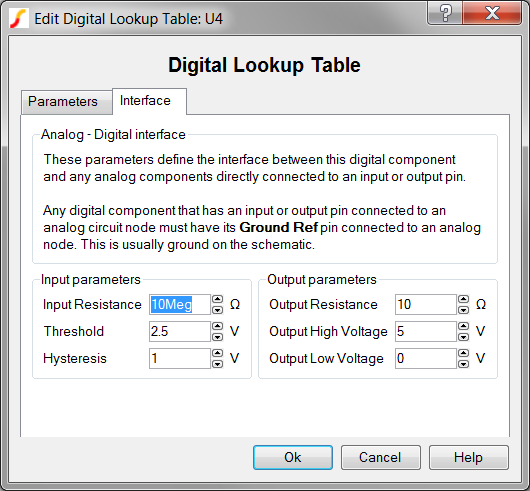
To define the parameters for the interface between this digital component and each analog component connected directly to an input or output pin, follow these steps from the Edit Digital Lookup Table dialog box:
| Label | Parameter Description | |||||||
Input Resistance |
Input resistance of each input pin |
|||||||
Threshold Hysteresis |
|
The Threshold (T) and Hysteresis (H) of the Schmitt trigger input buffer on each Lookup Table input. To determine the low-to-high threshold (TH) and the high-to-low threshold (TL), substitute Threshold (T) and Hysteresis (H) in each of the following formulas :
|
||||||
Output Resistance |
||||||||
Output High Voltage |
||||||||
Output Low Voltage |
||||||||
The digital lookup table can be defined with a dialog or with a points file.
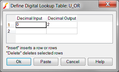
Using the dialog method, you can define up to 255 logical input states. The points definition is saved as a property on the digital lookup table symbol.
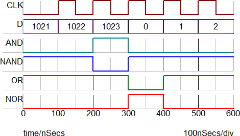
This method is often used for smaller table definitions, such as the 10-input AND and OR gates in this example. The input and output states are defined as the decimal equivalent of the input and output pins. For example, the 10-input AND gate in this example decodes 1023 (all 1's) and outputs a decimal 1, representing a logic low on the NAND output and a logic high on the AND output.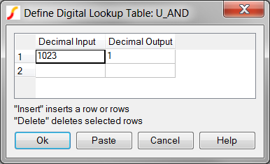
Using the file method, you can define the complete input space of 2Number of Input Bits. The points definition with this method is saved as a plain ASCII text file; before the simulation starts, the points file is read and used to configure the lookup table.
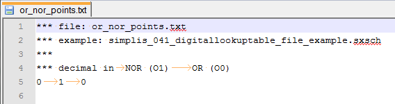
This method is often used for large or complicated table definitions although, as this example shows, a file method can be used for tables as small as a single input state definition. The following 10-input AND/NAND gate example demonstrates the file format, which uses tabs and spaces to delimit columns in the points definition file.
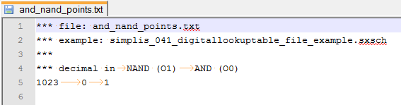
A points definition file example can be downloaded here: simplis_041_and_nand_points.txt. This file is also included in the following zip archive: simplis_041_digitallookuptable_file_example.zip.
The test circuit used to generate the waveform examples in the next section can be downloaded here: simplis_041_digitallookuptable_example.sxsch.
The same test circuit with lookup tables defined using the file method can be downloaded here: simplis_041_digitallookuptable_file_example.zip. In order to simulate this design, you need to unzip the archive to your local drive, and then open the schematic file in SIMetrix/SIMPLIS.
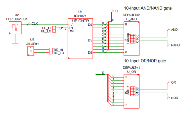
The digital lookup table examples use two lookup tables:
The AND/NAND logic gate is implemented with lookup table, U_AND; the OR/NOR gate is implemented with U_OR. The parameters for each lookup table are as follows:
In the following example, the initial condition of the counter is set to 1021 decimal, which allows the counter to reach the maximum count during a short simulation run. As the counter counts up, the AND/NAND gates transition at 1023, and the OR/NOR gates transition at 0 decimal.
The digital lookup table model is generated by a template script when the simulation is executed. For this reason, there is no fixed model which can be inserted into a netlist. The template script for this device is simplis_make_signal_source_model.sxscr, which you, as a licensed user, can download in a zip archive of all built-in scripts.
To download this zip file, follow these steps:
Note: You will be prompted to log in with the user name and password given to you when you registered.
*** ERRORS REPORTED BY SIMPLIS *******************************************
<<<<<<<< Error Message ID: 1179 >>>>>>>>
points file AND_NA~1.TXT
No data point has been defined in this file.
This model requires 1 data points to be defined.
*** END SIMPLIS ERROR REPORT ***
Error : The file 'and_nand_points.txt' contained some non-ascii characters

File read has been aborted
*** ERRORS REPORTED BY SIMPLIS ***

****************************************

<<<<<<<< Error Message ID: 1057 >>>>>>>>


input file file_path\SIMPLIS_Data/simplis_041_digitallookuptable_file_example.deck, line 76:

+  VOL=0  VOH=5  DEFAULT=2  OUT_DELAY=1e-011  NPTS=0 NUMBITS_OUT=2 NUMBITS_IN=10  FILE=AND_NA~1.TXT


A positive integer to represent

the value for `NPTS' is expected

at the location where `0'

occupies.
*** END SIMPLIS ERROR REPORT ***
*** ERRORS REPORTED BY SIMPLIS *******************************************
<<<<<<<< Error Message ID: 1179 >>>>>>>>
points file AND_NA~1.TXT, line 5
1023 0 1 *** illegal comment
^
Unexpected entry `***' when end of line
is expected while reading point #1.
*** END SIMPLIS ERROR REPORT ***