JK Flip Flop
In this topic:
Netlist entry
Axxxx j k clk set reset out nout model_name
Connection details
| Name | Description | Flow | Type |
| j | J input | in | d |
| k | K input | in | d |
| clk | Clock | in | d |
| set | Asynchronous set | in | d |
| reset | Asynchronous reset | in | d |
| out | Data output | out | d |
| nout | Inverted data output | out | d |
Model format
.MODEL model_name d_jkff parameters
Model parameters
| Name | Description | Type | Default | Limits |
| clk_delay | Delay from clk | real | 1nS | 1e-12 ???MATH???- \infty???MATH??? |
| set_delay | Delay from set | real | 1nS | 1e-12 ???MATH???0 - \infty???MATH??? |
| reset_delay | Delay from reset | real | 1nS | 1e-12 ???MATH???0 - \infty???MATH??? |
| ic | Output initial state | integer | 0 | ???MATH???0 - 2???MATH??? |
| rise_delay | Rise delay | real | 1nS | 1e-12 ???MATH???0 - \infty???MATH??? |
| fall_delay | Fall delay | real | 1nS | 1e-12 ???MATH???0 - \infty???MATH??? |
| jk_load | J,k load values (F) | real | 1pF | none |
| clk_load | Clk load value (F) | real | 1pF | none |
| set_load | Set load value (F) | real | 1pF | none |
| reset_load | Reset load value (F) | real | 1pF | none |
| family | Logic family | string | UNIV | none |
| in_family | Input logic family | string | UNIV | none |
| out_family | Output logic family | string | UNIV | none |
| out_res | Digital output resistance | real | 100 | ???MATH???0 - \infty???MATH??? |
| out_res_pos | Digital output res. pos. slope | real | out_res | ???MATH???0 - \infty???MATH??? |
| out_res_neg | Digital output res. neg. slope | out_res | ???MATH???0 - \infty???MATH??? | |
| min_sink | Minimum sink current | real | -0.001 | none |
| max_source | Maximum source current | real | 0.001 | none |
| sink_current | Input sink current | real | 0 | none |
| source_current | Input source current | real | 0 | none |
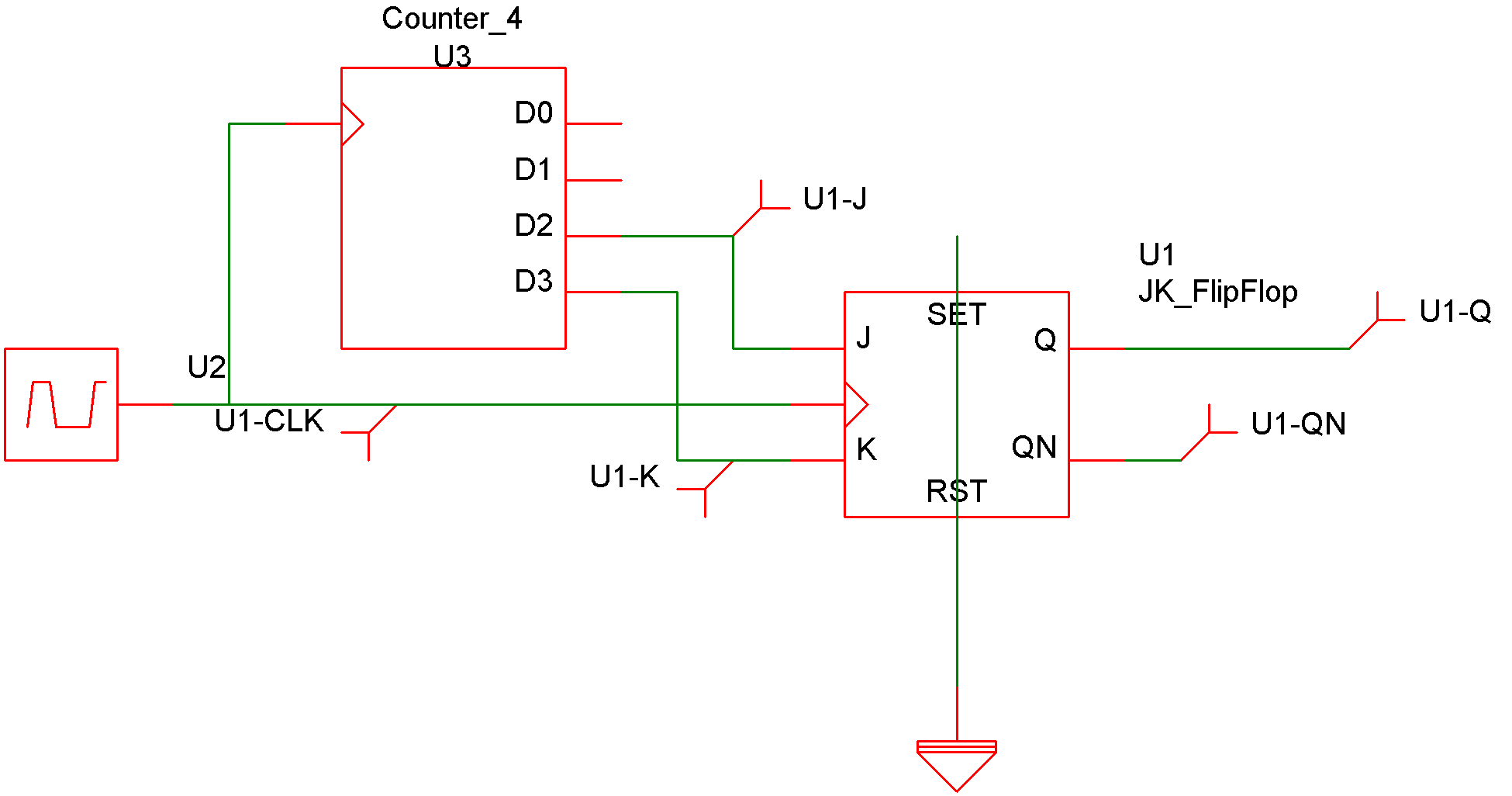
Device Operation
The following circuit and graph illustrate the operation of this device:
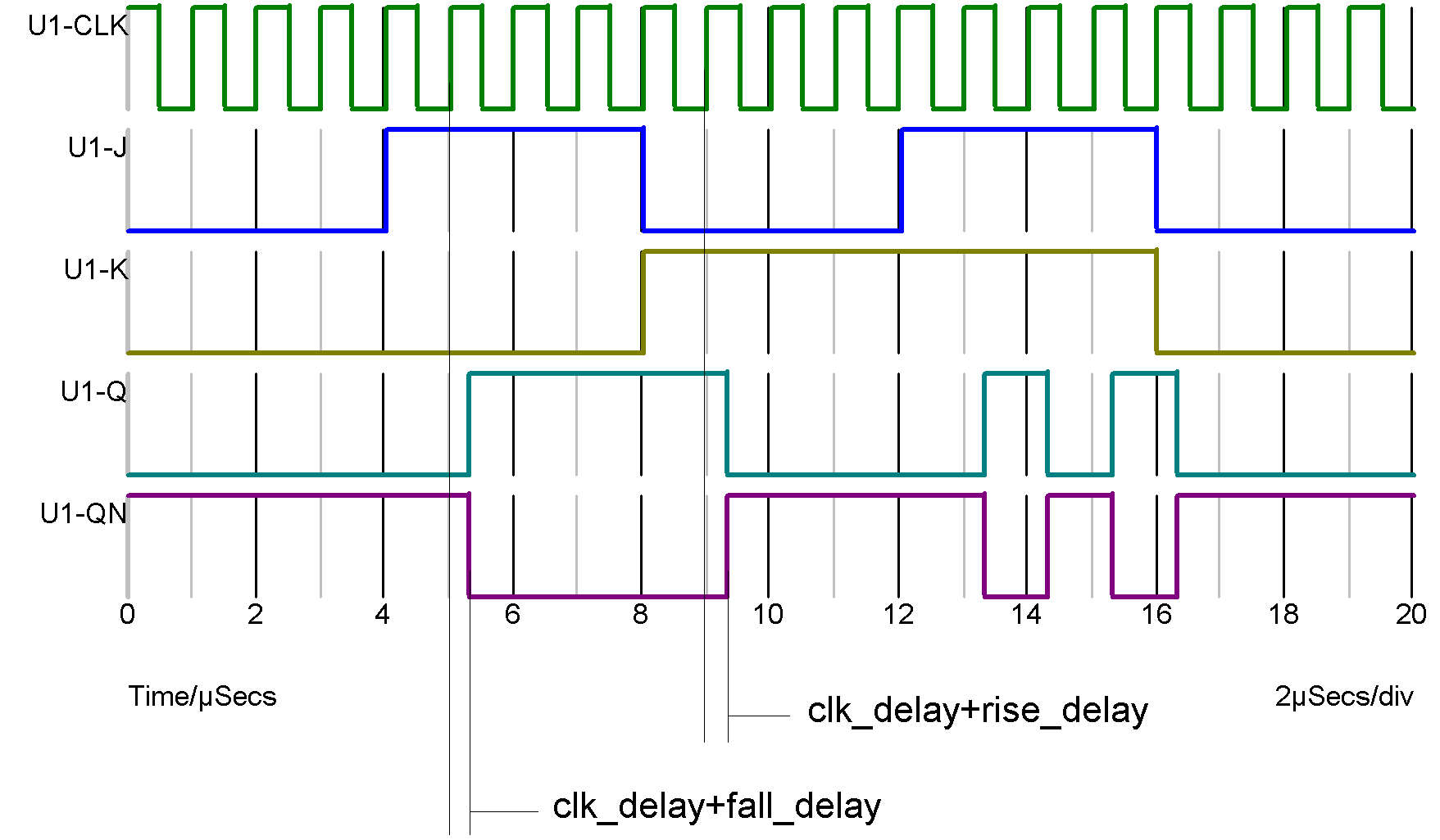
The following table describes the operation of the device when both inputs are at known states: The output can only change on a positive edge of the clock.
| J input | K input | Output |
| 0 | 0 | No change |
| 0 | 1 | 0 |
| 1 | 0 | 1 |
| 1 | 1 | toggle |
| J input | K input | old output | new output |
| 0 | 0 | 0 | 0 |
| 0 | 0 | 1 | 1 |
| 0 | 0 | X | X |
| 0 | 1 | 0 | 0 |
| 0 | 1 | 1 | 0 |
| 0 | 1 | X | 0 |
| 0 | X | 0 | 0 |
| 0 | X | 1 | X |
| 0 | X | X | X |
| 1 | 0 | 0 | 1 |
| 1 | 0 | 1 | 1 |
| 1 | 0 | X | 1 |
| 1 | 1 | 0 | 1 |
| 1 | 1 | 1 | 0 |
| 1 | 1 | X | X |
| 1 | X | 0 | 1 |
| 1 | X | 1 | X |
| 1 | X | X | X |
| X | 0 | 0 | X |
| X | 0 | 1 | 1 |
| X | 0 | X | X |
| X | 1 | 0 | X |
| X | 1 | 1' | 0 |
| X | 1 | X | X |
| X | X | 0 | X |
| X | X | 1 | X |
| X | X | X | X |
| ◄ Inverter | Arbitrary Logic Block ▶ |