In this Topic Hide
Initial conditions may be applied to capacitors and inductors and may also be applied to a single node using the .IC statement. Initial conditions force a voltage or current to be applied during the DC operating point analysis. Here we describe the various methods to apply an initial condition.
A voltage initial condition may be applied to a node using the .IC statement, see .IC. This method applies
the initial condition through a fixed resistor. In effect the following circuit is applied to the node during the DC operating point
then removed when the main analysis starts:
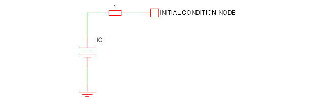
| .OPTIONS ICRES=1m |
The above sets the resistance to 1m$\Omega$.
Note that an initial condition may also be applied to a node or across a pair of nodes using a capacitor with a value of zero. See next section.
An initial condition may be defined for a capacitor using the IC parameter. The following
diagram shows how this is configured:
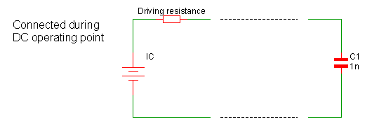
The actual interpretation of the IC parameter depends on the INITCONDMODE option setting:
| .OPTIONS INITCONDMODE=0|1|2 |
It also depends on the BRANCH parameter on the capacitor:
| Cxxxx n1 n2 capacitance IC=init_condition BRANCH=0|1 |
The different configurations have come about because of a need for compatibility with other simulators, namely SIMPLIS, Berkeley SPICE and PSpice.
The following table describes the various configurations:
|
IC defined |
BRANCH | INITCONDMODE | Configuration |
|---|---|---|---|
| NO | 0 | X | No initial condition applied |
| NO | 1 | X | Initial condition=0V, driving resistance=0$\Omega$ |
| YES | 0 | 0 | Berkeley SPICE compatible. Initial condition=IC only if UIC specified on .TRAN statement |
| YES | 0 | 1 |
SIMPLIS compatible. Initial condition=IC, driving resistance=0$\Omega$ |
| YES | 0 | 2 |
PSpice compatible. Initial condition=IC, driving resistance=ICRES (default=1$\Omega$) |
| YES | 1 | X |
SIMPLIS compatible. Initial condition=IC, driving resistance=0$\Omega$ |
Note that for full PSpice compatibility, the ICRES option should be set to 1m. Alternatively the option setting PSPICECOMPAT may be set which sets ICRES to 1m and INITCONDMODE to 2.
An initial condition may be defined for a inductor using the IC parameter. The following
diagram shows how this is configured:
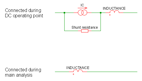
The actual interpretation of the IC parameter depends on the INITCONDMODE option setting:
| .OPTIONS INITCONDMODE=0|1|2 |
It also depends on the BRANCH parameter on the inductor:
| Lxxxx n1 n2 inductance IC=init_condition BRANCH=0|1 |
The different configurations have come about because of a need for compatibility with other simulators, namely SIMPLIS, Berkeley SPICE and PSpice.
The following table describes the various configurations:
|
IC defined |
BRANCH | INITCONDMODE | Configuration |
|---|---|---|---|
| NO | 1 | X | No initial condition applied |
| NO | 0 | X | Initial condition=0A, shunt resistance=$\infty$ |
| YES | 1 | 0 | Berkeley SPICE compatible. Initial condition=IC only if UIC specified on .TRAN statement |
| YES | 1 | 1 |
SIMPLIS compatible. Initial condition=IC, shunt resistance=$\infty$ |
| YES | 1 | 2 |
PSpice compatible. Initial condition=IC, shunt resistance=1e9 $\Omega$ |
| YES | 0 | X |
SIMPLIS compatible. Initial condition=IC, shunt resistance=$\infty$ |
|