In this Topic Hide
Most circuits require some form of input signal such as a pulse or sine wave. Such signals - or stimuli - are specified using a voltage or current source which is placed on the schematic in the usual way. A number of different types of source are available. These are described in the following sections.
This is used to create a time domain signal for transient analysis. This generator will work in both SIMetrix and SIMPLIS modes of operation. To place one of these devices, select menu for a voltage source or for a current source.
To specify the signal for the source, select then choose the popup menu or press F7. This will bring up the dialog box shown below. (In SIMPLIS simulation mode it will have an additional check box - see notes below)
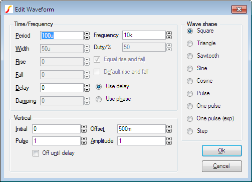
Select the wave shape on the right hand side then enter the parameters as appropriate. The following notes provide details on some of the controls.
This device can be used to describe a piece wise linear source. A PWL source can describe any arbitrary wave shape in terms of time-voltage or time-current pairs. To place a PWL source select menu or .
To edit the device, select it and press F7 or popup menu. This will open the Edit PWL Dialog which allows you to enter time and voltage/current values.
As well as entering values individually, you can also paste them from the Windows clipboard by pressing the Paste button or ctrl-V. The values can be copied to the clipboard using a text editor. The values may be separated by spaces, tabs, commas or new lines.
PWL sources may be used in both SIMetrix and SIMPLIS modes, but note that in SIMPLIS, PWL sources are limited to 256 points. Larger definitions are allowed in SIMetrix mode, but for very large PWL definitions, a PWLFILE source will See the "Analog Device Reference" in the Simulator Reference Manual for more information.
In SIMPLIS mode, a check box titled Source Idle during POP and AC analyses will also be shown. This will be checked by default meaning that the source is inactive in POP and AC analyses.
Select menu or to place a fixed voltage or current source. These devices work in both SIMetrix and SIMPLIS modes.
The small signal analysis modes, AC sweep and Transfer Function, require AC sources for their input stimulus.
To place an AC source select menu or .
You can also use a Universal Source (see below) for the AC source for SIMetrix (i.e. not SIMPLIS) simulations. Be sure to check the Enable AC check box in the Universal Source.
All of the sources described above can be used in both SIMetrix and SIMPLIS modes of operation. In SIMetrix mode there is also a Universal source which provides the function of transient, AC and DC sources all in one device. In addition, the Universal source may be used to create a random noise source.
To place a universal source, select menu or .
To edit a universal source, select the device and press F7 or popup menu . This will display the following dialog box:
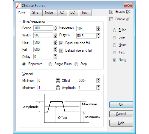
Pulse, sine, noise and DC waveforms may be specified using the tab sheets of the same name. You can also specify a Piece wise linear source, exponential source or a single frequency FM source. To enter one of these select the Text tab and enter the appropriate syntax for the source. Please refer to Voltage source in the Simulator Reference Manual for more information on these sources. The AC sheet is for AC analysis only.
With the universal source, you can specify transient, AC and DC specifications simultaneously. This is not possible with any of the other sources.
The digital pulse device creates a single shot or repetitive pulse in the digital event driven domain. As digital and analog nodes can be freely interconnected, analog parts may be connected to it but it is more efficient to use an analog pulse generator for this purpose.
To Place a Digital Pulse
Device Operation This device supplies a repetitive or single pulse of defined period, delay and width. Optionally, the device may be specified to have an open emitter output allowing several pulse sources to be wire OR'ed to create complex pulses. All 5 main .MODEL parameters may also be specified on the device line as instance parameters in which case they override any values specified in the .MODEL control.
The digital signal source provides a multi bit arbitrary digital signal defined in a file. There is no standard schematic part for this device as it can be defined with an arbitrary number of outputs. For more information, see Simulator Reference Manual/Digital Mixed Signal Device Reference/Digital Signal Source.
Generates a sequence of sinusoidal bursts with a user defined number of cycles per burst, burst frequency and tone frequency.
Use menu then place device in the usual way. Editing the device will bring up a dialog with 6 parameters:
| Parameter | Description |
|---|---|
| Burst Freq. | Burst frequency |
| Tone Freq. | Frequency of the sinusoidal tone |
| Num Tone Cycles | Number of sinusoidal cycles in each burst |
| Peak | Peak voltage |
| Offset | Offset voltage |
| Points Per Cycle | Minimum number of time steps in each sinusoidal cycle. Increasing this number will improve the accuracy of the simulation at the expense of simulation speed |
Generate a sinusoidal signal with linearly increasing frequency.
Use menu then place in the usual manner. Editing the device will bring up a dialog with 6 parameters:
| Parameter | Description |
|---|---|
| Start Frequency | Starting frequency |
| End Frequency | Frequency at the end of the ramp |
| Interval | Time taken to ramp from start frequency to end frequency |
| Peak | Peak voltage |
| Offset | Offset voltage |
| Points Per Cycle | Minimum number of time steps in each sinusoidal cycle. Increasing this number will improve the accuracy of the simulation at the expense of simulation speed |
Generates a symmetrical bidirectional pulse waveform.
Use menu then place device in the usual way. Editing the device will bring up a dialog with 3 parameters:
| Parameter | Description |
|---|---|
| P-P Voltage | Peak to peak voltage |
| Frequency | Pulse frequency |
| Delay | Delay after start |
|