
|
In this Topic Hide
We will now show how to make a simple gain block. Here is the Verilog-A design:
| `include "disciplines.vams" |
| module gain_block(in, out) ; |
| electrical in, out ; |
| parameter real gain=1.0 ; |
| analog |
| V(out) <+ V(in)*gain ; |
| endmodule |
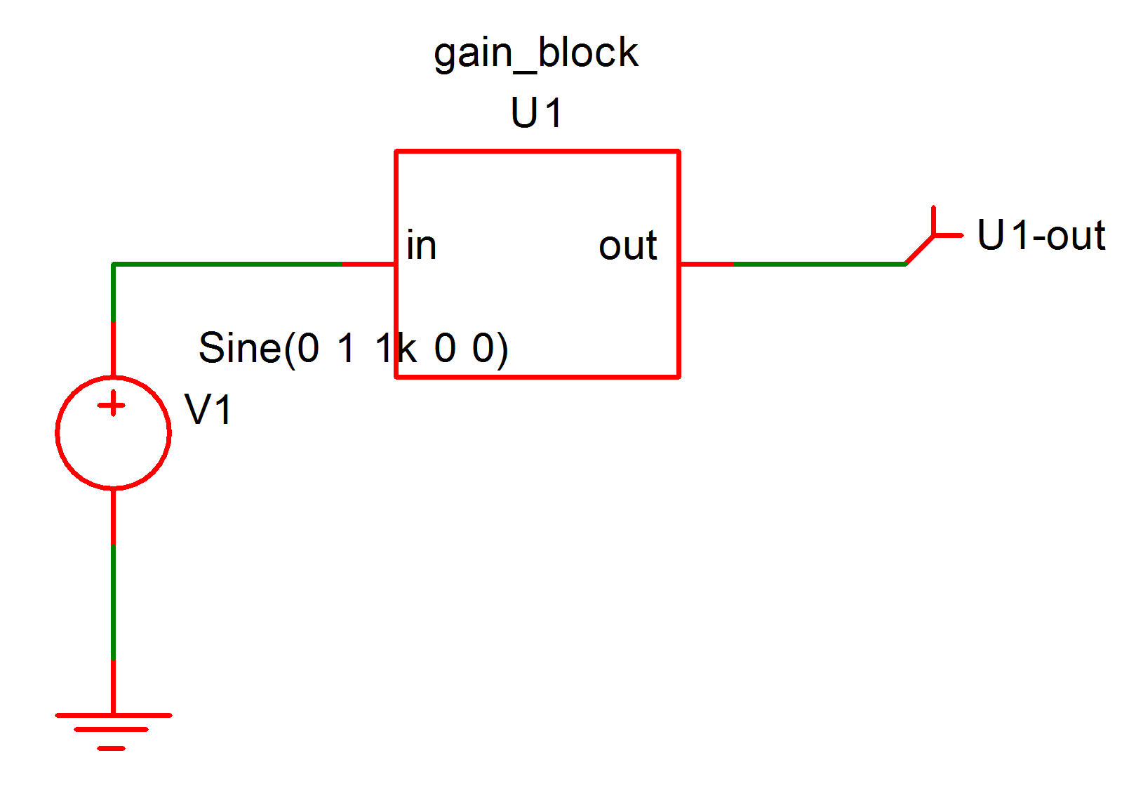
You may like to enter the above example in the same manner as the previous hello world example. We suggest entering this circuit:

When using the menu for the above definition, you will notice a dialog box appear asking the location for the device's pins. You would not have seen this with the hello world example as that device does not have any pins. Choose 'left' for 'in' and 'right' for 'out'.
We have supplied the above pre-built. See Examples/Manual/gain-block. All the examples used in this manual are available from Examples/Manual. However, you may find it more instructive to enter the code and schematics manually. But we would advise against copying and pasting from this document as some characters may not copy correctly. We suggest type in by hand - note that the quote character before include is a 'back tick' - usually the key at the far left of the row of numbers on US, UK and other keyboards.
Run the above in the usual way. You should see an output that follows the input; that is a 1V 1kHz sine wave.
In the above definition we have introduced two 'module ports' to the module definition. These define connection terminals and the generated symbol shows these as pins 'in' and 'out'.
The line:
| V(out) <+ V(in)*gain ; |
defines the relationship between the module ports out and in. This is known as a branch contribution and is one of the most important Verilog-A concepts. Branch contributions define a relationship that the simulator must maintain between the 'probes' (V(in) in the above) on the right hand side and the 'source' (V(out) above) on the left hand side. They behave in the same way as arbitrary source devices. The above, for example, is equivalent to a SIMetrix netlist line like this:
| B1 out 0 v = V(in) * gain |
Branch contributions, however, differ from arbitrary sources in that they are additive. Successive branch contributions with the same left hand side add to each other. This applies to both voltage and current sources. For example:
| V(out) <+ V(in)*gain ; |
| V(out) <+ 1.0 ; |
is the same as:
| V(out) <+ V(in)*gain + 1.0 ; |
The V() function in the above is known as an access function. Access functions may have one or two arguments each of which must refer to a port or internal node. If two arguments are provided, V() accesses the potential between the two nodes. If only a single node is supplied, it accesses the potential between that node and ground.
The access function I() access the current flowing between its two nodes. As with the voltage access function, if only a single node is provided, the second node is implicitly ground.
The access functions V() and I() are not defined as language keywords but are in fact defined by the electrical discipline contained within the disciplines.vams file.
| parameter real gain=1.0 ; |
defines a parameter and gives it a default value of 1.0. This value can be edited at the netlist level. If you used a generated symbol or our pre-built example, double click the device U1, then enter:
| gain=5 |
Now rerun the schematic. Notice the output amplitude increase to 5V peak.
Finally, you will notice two other lines not in the hello world example:
| electrical in, out ; |
defines the discipline for the module ports in this case 'electrical'. Verilog-A supports other disciplines such as thermal, mechanical and rotational allowing simulation of physical processes other than electrical and electronic. The definitions of these other disciplines are defined in the disciplines.vams file which is included using the line:
| `include "disciplines.vams" |
Nearly all Verilog-A definitions include this line at the top of the file. We excluded it from the hello world example as that did not need it.
|