DVM - Design Verification Module
DVM - Design Verification Module
|
The AC glitch input source simulates a "glitch" disturbance in the AC line. The glitch amplitude can be greater or less than the line voltage. The phase angle and duration of the glitch are programmable. This source can be configured to simulate a broad range of abnormal AC Line voltage conditions.
The AC Glitch source is not used in any test objectives. You can set a AC Source to a Glitch type source using the testplan syntax below.
In this Topic Hide
Model Name |
AC Glitch Input Source |
|
Simulator |
|
This device is compatible with both the SIMetrix and SIMPLIS simulators. |
Parts Selector |
DVM ▶Source ▶DVM Input Source w/ AC Line Support |
|
Symbol Library |
None - the symbol is automatically generated when placed or edited. |
|
Model File |
SIMPLIS_DVM_ADVANCED.lb |
|
| Subcircuit Name | SIMPLIS_DVM_ADVANCED_SOURCE_AC_GLITCH | |
| Schematic | 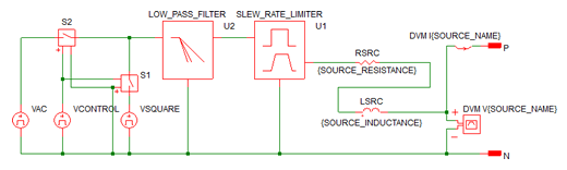 |
|
The following table explains the relevant parameters.
| Parameter Name | Default | Data Type | Range | Units | Parameter Description |
AC_VOLTAGE1 |
115 | Real | min: 0 | V | The RMS value of the source during normal operating conditions. |
AC_VOLTAGE2 |
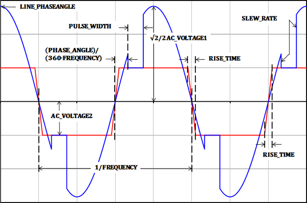
230 | Real | min:0 | V | The peak voltage of the source during a glitch event. See the waveforms section for details. |
DC_VOLTAGE |
5 | Real | V | The DC voltage offset of the source | |
FREQUENCY |
50 | Real | min: >0 | Hz | The frequency of the source |
F_CORNER |
1Meg | Real | min: >0 | Hz | The corner frequency for the internal low pass filter. The number of poles is set by the N_ORDER parameter. |
LINE_PHASEANGLE |
0 | Real | 0- 360 | ° | Sets the source phase angle at time=0. Most often used in three phase systems to set the phase angle of each phase. |
N_ORDER |
0 | Real | 0 - 3 | The number of poles in the filter. Set to 0 to remove the filter from the design. | |
PHASE_ANGLE |
0 | Real | 0 - 180 | ° | Sets the phase angle where the glitch disturbance occurs. |
PULSE_WIDTH |
200u | Real | min:0 | s | The duration of the line glitch in seconds. |
RISE_TIME |
10u | Real | min:>0 | s | The rise and fall time of the internal square wave source. See the waveforms section for details. |
SLEW_RATE |
10Meg | Real | max: | V/s | The maximum slew rate of the voltage source |
SOURCE_INDUCTANCE |
795.8u | Real | min: 0 | H | Sets the inductance of the line source |
SOURCE_NAME |
SRC | String | n/a | n/a | Name of the DVM source. This name cannot contain spaces. |
SOURCE_RESISTANCE |
0.4 | Real | min:0 | Ω | Sets the source resistance of the source. |
PHASE_ANGLE |
0 | Real | 0 - 360 | ° | Sets the phase angle where the glitch disturbance occurs. |
To set a managed DVM source to use the AC Glitch subcircuit, the source symbol must be set to support AC line sources. Then, to set the source definition to a AC Glitch source, place a AcGlitch() testplan entry in a Source column.
The AcGlitch() testplan entry has the following syntax with the arguments taken from the list of parameters above.
AcGlitch(REF, LINE_RANGE, NOMINAL_VOLTAGE,
GLITCH_VOLTAGE,
FREQUENCY, PHASE_ANGLE, PULSE_WIDTH,
RISE_TIME)
AcGlitch(REF, LINE_RANGE, NOMINAL_VOLTAGE,
GLITCH_VOLTAGE,
FREQUENCY, PHASE_ANGLE, PULSE_WIDTH,
RISE_TIME, OPTIONAL_PARAMETER_STRING)
| Argument | Range | Description |
REF |
n/a |
The actual reference designator of the DVM Source or the generic syntax of INPUT:n where n is an integer indicating a position in the list of managed DVM sources. |
LINE_RANGE |
LL or HL | The line range to select the correct symbolic voltage value. This can only be the two strings LL or HL. |
NOMINAL_VOLTAGE |
min:0 |
The RMS voltage for the input source during the normal operating conditions. The voltage can be a numeric value or a symbolic value, such as a percentage of nominal input voltage. Symbolic values use the LINE_RANGE parameter to find the correct symbolic value. |
GLITCH_VOLTAGE |
min:0 |
The peak voltage for the input source during the glitch event. The voltage can be a numeric value or a symbolic value, such as HL_Maximum. Symbolic values use the LINE_RANGE parameter to find the correct symbolic value. |
FREQUENCY |
min: > 0 |
The AC line frequency of the input source. This is used to both set the frequency of the input source and to set the simulation timing. The frequency can be a numeric or a symbolic value, such as F_High or F_Low. |
PHASE_ANGLE |
0-180 |
The phase angle of the glitch disturbance |
PULSE_WIDTH |
min:>0 |
The duration of the glitch disturbance |
RISE_TIME |
mon:>0 |
The rise time of the underlying AC square wave sources |
OPTIONAL_PARAMETER_STRING |
n/a |
Parameter string with any of the other parameters from the parameter table above* |
* If more than one parameter is specified, join the parameter key-value pairs with a space, as shown in the example below. The order of the parameter names does not matter.
This example uses the optional parameter LINE_PHASEANGLE set to 90°, and a PHASE_ANGLE of 30°. The duration of the glitch event is set with the PULSE_WIDTH parameter. The voltage transition between the normal AC voltage and the glitch voltage is limited by the combination of the slew rate limiter and the programmable low pass filter.
© 2015 simplistechnologies.com | All Rights Reserved
