DVM - Design Verification Module
DVM - Design Verification Module
|
The AC quasi-square-wave input source models the line voltage typically generated by inverters.
The AC Quasi-Square-Wave source (QSW) is not used in any test objectives. You can set a AC Source to a QSW type source using the testplan syntax below.
In this Topic Hide
Model Name |
AC Quasi-Square-Wave Input Source |
|
Simulator |
|
This device is compatible with both the SIMetrix and SIMPLIS simulators. |
Parts Selector |
DVM ▶Source ▶DVM Input Source (w/ AC Line Support) |
|
Symbol Library |
None - the symbol is automatically generated when placed or edited. |
|
Model File |
SIMPLIS_DVM_ADVANCED.lb |
|
| Subcircuit Name | SIMPLIS_DVM_ADVANCED_SOURCE_AC_QSW | |
| Schematic | 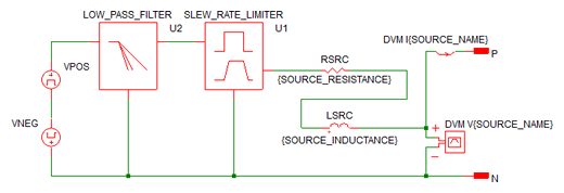 |
|
The following table explains the relevant parameters.
| Parameter Name | Default | Data Type | Range | Units | Parameter Description |
AC_VOLTAGE1 |
115 | Real | min: 0 | V | The RMS value of the source during normal operating conditions. |
FREQUENCY |
50 | Real | min: >0 | Hz | The frequency of the source |
F_CORNER |
1Meg | Real | min: >0 | Hz | The corner frequency for the internal low pass filter. The number of poles is set by the N_ORDER parameter. |
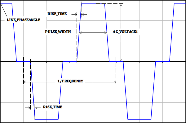
LINE_PHASEANGLE |
0 | Real | 0- 360 | ° | Sets the source phase angle at time=0. Most often used in three phase systems to set the phase angle of each phase. |
N_ORDER |
0 | Real | 0 - 3 | The number of poles in the filter. Set to 0 to remove the filter from the design. | |
PULSE_WIDTH |
200u | Real | min:0 | s | The duration of the pulse in seconds. |
RISE_TIME |
10u | Real | min:>0 | s | The rise and fall time of the internal square wave source. See the waveforms section for details. |
SLEW_RATE |
10Meg | Real | max: | V/s | The maximum slew rate of the voltage source |
SOURCE_INDUCTANCE |
795.8u | Real | min: 0 | H | Sets the inductance of the line source |
SOURCE_NAME |
SRC | String | n/a | n/a | Name of the DVM source. This name cannot contain spaces. |
SOURCE_RESISTANCE |
0.4 | Real | min:0 | Ω | Sets the source resistance of the source. |
To set a managed DVM source to use the AC Quasi-Square-Wave subcircuit, the source symbol must be set to support AC line sources. Then, to set the source definition to a AC QSW source, place a AcQsw() testplan entry in a Source column.
The AcQsw() testplan entry has the following syntax with the arguments taken from the list of parameters above.
AcQsw(REF, LINE_RANGE, AC_VOLTAGE1,
FREQUENCY,
PULSE_WIDTH, RISE_TIME)
AcQsw(REF, LINE_RANGE, AC_VOLTAGE1,
FREQUENCY,
PULSE_WIDTH, RISE_TIME, OPTIONAL_PARAMETER_STRING)
| Argument | Range | Description |
REF |
n/a |
The actual reference designator of the DVM Source or the generic syntax of INPUT:n where n is an integer indicating a position in the list of managed DVM sources. |
LINE_RANGE |
LL or HL | The line range to select the correct symbolic voltage value. This can only be the two strings LL or HL. |
AC_VOLTAGE1 |
min:0 |
The pulse voltage for the input source. The voltage can be a numeric value or a symbolic value, such as a percentage of nominal input voltage. Symbolic values use the LINE_RANGE parameter to find the correct symbolic value. |
FREQUENCY |
min: > 0 |
The AC line frequency of the input source. This is used to both set the frequency of the input source and to set the simulation timing. The frequency can be a numeric or a symbolic value, such as F_High or F_Low. |
PULSE_WIDTH |
min:>0 |
The pulse duration of the source |
RISE_TIME |
mon:>0 |
The rise and fall times of the source |
OPTIONAL_PARAMETER_STRING |
n/a |
Parameter string with any of the other parameters from the parameter table above* |
* If more than one parameter is specified, join the parameter key-value pairs with a space, as shown in the example below. The order of the parameter names does not matter.
This example uses the optional parameter LINE_PHASEANGLE set to 90°. The pulse width is set to 30% of the period and the rise time to 5% of the period.
© 2015 simplistechnologies.com | All Rights Reserved
