SystemDesigner
SystemDesigner
|
SystemDesigner includes a complete PWM generator based on the Texas Instruments Piccolo™ enhanced PWM (ePWM) module. This PWM module can generate almost any PWM pattern, including variable frequency (LLC) or phase-shifted topologies. The ePWM module can generate Start-of-Conversion (SOC) signals at any point in the PWM cycle, allowing you to accurately model the time-domain sampling behavior of the converter. The SOC signals are then routed globally to all SystemDesigner ADC converters through the global Start of Conversion routing system.
* Piccolo is a trademark of Texas Instruments Incorporated.
In this Topic Hide
Model Name: |
SystemDesigner TI Piccolo ePWM Module |
|
Simulator: |
|
This device is compatible with the SIMPLIS simulator. |
Parts Selector |
SystemDesigner Functions (max. 32 bit) | Probes |
|
Symbol Library: |
None - the symbol is automatically generated when placed or edited. |
|
Model File: |
SIMPLIS_SystemDesigner_ePWMs.lb |
|
Subcircuit Name: |
SIMPLIS_SD_EPWM_V7p2 |
|
Symbols: |
Various - The symbol is automatically drawn to match the required pins. |
|
Multiple Selections: |
Only one SystemDesigner TI Piccolo ePWM Module may be edited at a time. |
|
This model was carefully constructed from publicly available information including the two TI data sheets:
Because the two TI data sheets completely describe the behavior of the ePWM, the details of the ePWM module are not documented in the SIMetrix/SIMPLIS help system.
The full implementation of the Piccolo DSP includes eight submodules. Five of these eight submodules are included in the SystemDesigner ePWM module:
The following modules are not included:
The ePWM module is configured using the same register names as noted
in the TI data sheets. Instead of setting the register values in code,
the SystemDesigner
ePWM uses a parameter editing dialog, which is shown below with the tool
tip for the Time-Base Period Register. Each edit control on the dialog
has a similar tool tip explaining the usage of the parameter or register
value. 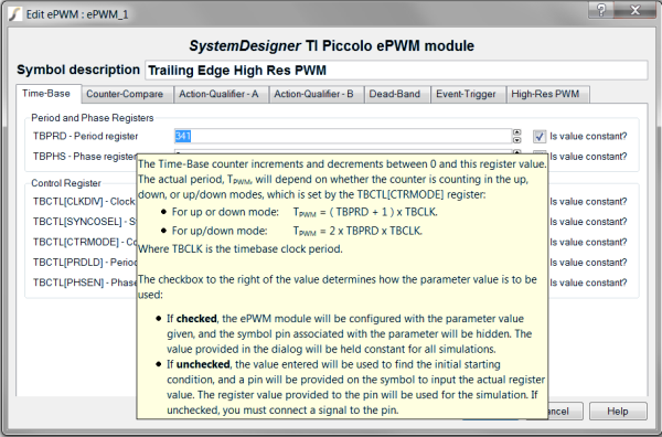
On the parameter editing dialog, most edit controls have a check box to tell the program if the register value is constant. Checking Is value constant? fixes that value for the entire simulation. The pin normally associated with that register value is hidden on the symbol, making the symbol smaller. In the dialog-box illustration above, the Time-Base period register, TBPRD, is held constant because this ePWM is configured for fixed-frequency operation.
At the bottom of the editing dialog is a check box that determines if the debug pins are added to the symbol:
Also at the bottom of the editing dialog is a check box that determines the generated symbol size:
Each ePWM module has a Symbol description label to describe how the ePWM is configured. The description is not used in the simulation, and the program never changes the label value. For example, if you place a trailing-edge-configured ePWM and then change the register values to configure the ePWM as a leading edge ePWM, the label will not change.
Listed below are links to download examples using each of the pre-configured ePWM modules:
© 2015 simplistechnologies.com | All Rights Reserved
