SystemDesigner
SystemDesigner
|
The SystemDesigner Limiter limits the maximum and minimum amplitudes of a SystemDesigner bus. The maximum and minimum amplitudes can be any integer value. The Limiter output is a SystemDesigner bus with a 32-bit signed-integer or floating-point result.
The propagation delay can be defined as a fixed time, as asynchronous to any clock, or as a synchronous delay where the delay is a number of SystemDesigner-clocks cycles. In this release of SystemDesigner, the synchronous delay is supported only for integer-sampled data simulations.
In this Topic Hide
Model Name: |
SystemDesigner Limiter |
|
Simulator: |
|
This device is compatible with the SIMPLIS simulator. |
Parts Selector |
SystemDesigner Functions (max. 32 bit) |
|
Symbol Library: |
SIMPLIS_SystemDesigner.sxslb |
|
Model File: |
SIMPLIS_SystemDesigner.lb |
|
Subcircuit Name: |
SIMPLIS_SD_LIMITER_32 |
|
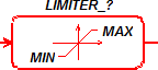
Symbols: |
|
|
Multiple Selections: |
Only one device at a time can be edited. |
|
To configure the Limiter, double click the symbol to open the parameter editing dialog.
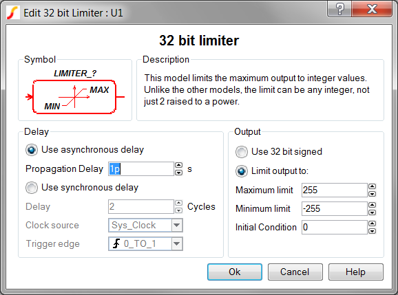
| Label | Parameter Description |
Use asynchronous delay |
Implements a combinatorial model where the output voltage changes in response to the input voltage(s) change after a propagation delay. |
Propagation Delay |
The propagation delay from an input change to an output change in seconds. |
Use synchronous delay |
In response to an input voltage change, the output voltage changes after a designated number of clock cycles. |
Delay |
The propagation delay from an input change to an output change in number of clock cycles. The output will not change until the number of clock cycles has been reached. The output will then change state only on the selected Clock source edges specified by Trigger edge. |
Clock source |
|
Trigger edge |
|
Use 32 bit signed |
The full 32-bit signed data is output. |
Limit output to: |
The output is limited to a Signed or Unsigned number with a designated number of bits. |
Maximum limit |
The limit value which clamps the maximum output for this model |
Minimum limit |
The limit value which clamps minimum output for this model |
Initial Condition |
Initial condition of the output at time=0. Value is the output bus represented in decimal format. |
The Limiter circuit example can be downloaded here: simplis_115_systemdesigner_limiter_example.zip. In order to simulate this design, follow these steps:
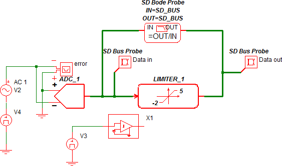
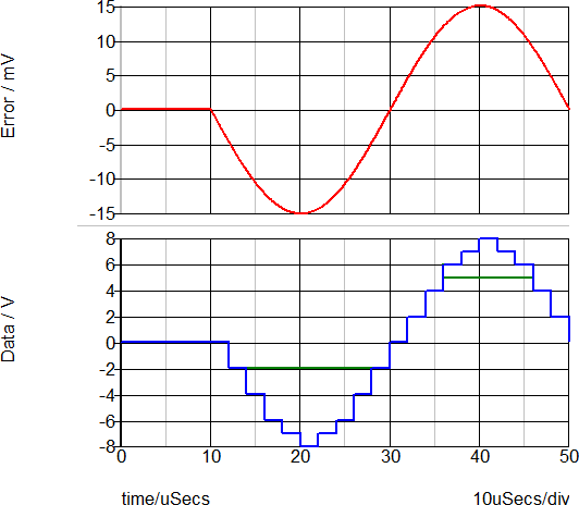
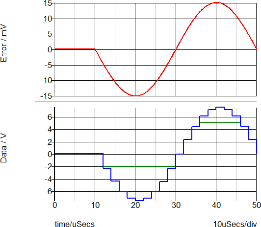
The circuit example below uses an ADC to generate the input to the Limiter LIMITER_1. The Limiter is set with the maximum limit of 5 and the minimum limit of -2. The output is limited to values between these limit values for all simulations.
During floating-point simulations, the Limiter also limits the input signal, producing a limited double-precision floating-point output.
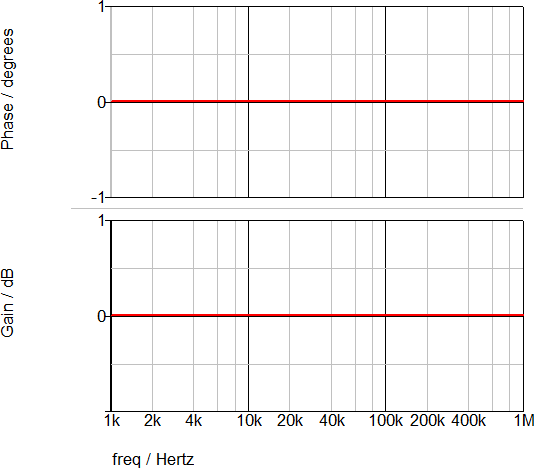
The AC transfer function for the Limiter is shown below. As expected, the gain is 0dB with no phase change.
© 2015 simplistechnologies.com | All Rights Reserved