SIMPLIS Parts
SIMPLIS Parts
|
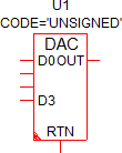
The Digital-to-Analog Converter models a generic DAC.
In this Topic Hide
Model Name: |
Digital-to-Analog Converter |
|
Simulator: |
|
This device is compatible with the SIMPLIS simulator. |
Parts Selector |
Digital Functions | A to D / D to A |
|
Symbol Library: |
None - the symbol is automatically generated when placed or edited. |
|
Model File: |
None - the device model is generated before simulation. |
|
Subcircuit Name: |
SIMPLIS_DIGI1_D_D2A_CONVERTER_Y |
|
Symbols: |
|
|
Multiple Selections: |
Only one device at a time can be edited. |
|
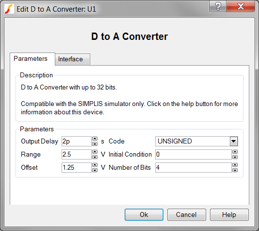
To configure the digital-to-analog converter, follow these steps:
| Label | Parameter Description |
Output Delay |
Delay from when the input state changes until the output changes |
Range |
Analog output voltage range |
Offset |
Midpoint of analog output voltage range |
Code |
Encoding scheme for binary inputs of the DAC |
Initial Condition |
Initial condition of the DAC output at time=0 |
Number of Bits |
Number of input bits for this D-to-A Converter |
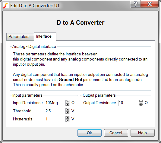
To define the parameters for the interface between this digital component and each analog component connected directly to an input or output pin, follow these steps from the Edit Digital-to-Analog Converter dialog box:
| Label | Parameter Description | |||||||
Input Resistance |
Input resistance of each input pin |
|||||||
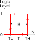
Threshold Hysteresis |
|
The Threshold (T) and Hysteresis (H) of the Schmitt trigger input buffer on each DAC input. To determine the low-to-high threshold (TH) and the high-to-low threshold (TL), substitute Threshold (T) and Hysteresis (H) in each of the following formulas :
|
||||||
Output Resistance |
||||||||
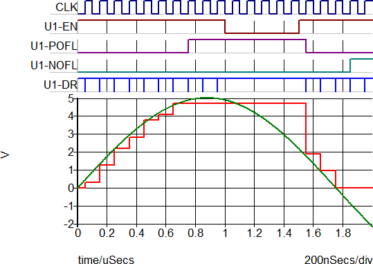
The test circuit used to generate the waveform examples in the next section can be downloaded here: simplis_062_dac_example.sxsch.
Because this digital-to-analog converter model is generated by a template script when the simulation is executed, a fixed model cannot be inserted into a netlist. The template script for this device is simplis_make_a2d_model.sxscr, which you, as a licensed user, can download in a zip archive of all built-in scripts.
To download this zip file, follow these steps:
Note: You will be prompted to log in with the user name and password given to you when you registered.