SIMPLIS Parts
SIMPLIS Parts
|
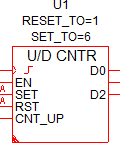
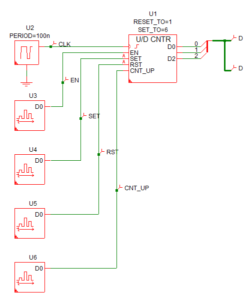
The Up/Down Counter models a generic up or down counter with between 2 and 32 output bits. The direction of the counter is based on the CNT_UP pin.
For a counter which counts up, see the Up Counter. For a counter that counts down, see Down Counter.
In this Topic Hide
Model Name: |
Up/Down Counter |
|
Simulator: |
|
This device is compatible with the SIMPLIS simulator. |
Parts Selector |
Digital Functions | Counters |
|
Symbol Library: |
None - the symbol is automatically generated when placed or edited. |
|
Model File: |
None - the device model is generated before simulation. |
|
Subcircuit Name: |
|
|
Symbols: |
|
|
Multiple Selections: |
Only one device at a time can be edited. |
|
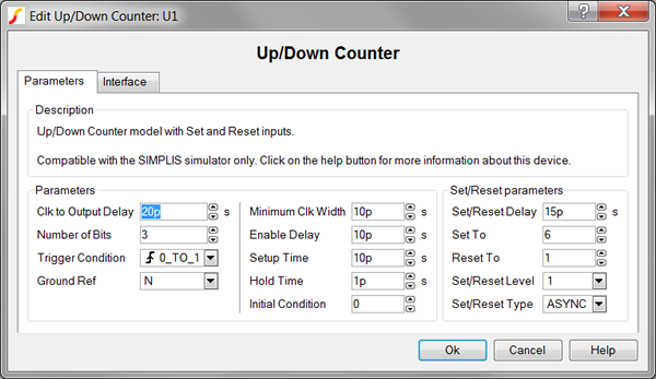
To configure the up/down counter, follow these steps:
| Label | Parameter Description | ||||||
Clock to Output Delay |
Delay from the triggering clock event until the outputs change |
||||||
Number of Bits |
Number of output bits for the counter |
||||||
Trigger Condition |
Determines the triggering condition of the counter clock pin:
|
||||||
Ground Ref |
Determines whether or not a device has a ground
reference pin. |
||||||
Minimum Clock Width |
Minimum valid clock width. Clock widths less than this parameter will not trigger the counter. |
||||||
Enable Delay |
Delay from when the enable pin goes active until the clock is enabled and the counter starts counting |
||||||
Setup Time |
Minimum time before the triggering clock event that the input signalss must remain steady so that a valid change in each input state is recognized. |
||||||
Hold Time |
Minimum time after the triggering clock event that the input signalss must remain steady so that a valid change in each input state is recognized. |
||||||
Initial Condition |
Initial condition of the counter output in decimal |
||||||
Set/Reset Delay |
Delay from when the SET and RST pin goes active until the counter output is reset |
||||||
Asynchronous Set/Reset Parameters |
|||||||
Set To |
Determines the value of the counter output when the SET pin goes active. To set to the maximum count value, assign a value of -1. |
||||||
Reset To |
Determines the value of the counter output when the RST pin goes active. To reset to 0, assign a assign value of -1 or 0. |
||||||
Set/Reset Level |
|
||||||
Set/Reset Type |
|
||||||
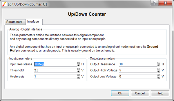
To define the parameters for the interface between this digital component and each analog component connected directly to an input or output pin, follow these steps from the Edit Analog-to-Digital Converter dialog box:
| Label | Parameter Description | |||||||
Input Resistance |
Input resistance of each input pin |
|||||||
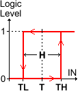
Threshold Hysteresis |
|
The Threshold
(T) and Hysteresis (H) of the Schmitt trigger
input buffer on each Counter input. To determine the low-to-high
threshold (TH) and the high-to-low threshold (TL),
substitute Threshold (T) and Hysteresis (H)
in each of the following formulas :
|
||||||
Output Resistance |
||||||||
Output High Voltage |
||||||||
Output Low Voltage |
||||||||
The following truth table assumes a Trigger Condition=0_TO_1 which represents a rising edge clocked Counter.
Inputs |
Outputs |
Action |
||||
EN |
SET |
RST |
CNT_UP |
CLK |
D0..Dn |
|
1 |
0 |
0 |
0 |
 |
Count - 1 |
Count down |
1 |
0 |
0 |
1 |
|
Count + 1 |
Count up |
0 |
0 |
0 |
0 |
Last count |
Retain last count |
|
1 |
0 |
Set To parameter value |
Set the counter to the Set To parameter value |
|||
0 |
1 |
Reset To parameter value |
Set the counter to the Reset To parameter value |
|||
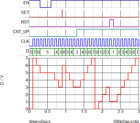
The test circuit used to generate the waveform examples in the next section can be downloaded here: simplis_030_updowncounter_example.sxsch.
Because this up/down-counter model is generated by a template script when the simulation is executed, a fixed model cannot be inserted into a netlist. The template script for this device is simplis_make_counter_model.sxscr, which you, as a licensed user, can download in a zip archive of all built-in scripts.
To download this zip file, follow these steps:
Note: You will be prompted to log in with the user name and password given to you when you registered.