SIMPLIS Parts
SIMPLIS Parts
|
The Digital Signal Source provides a flexible way to define digital circuit stimulus. For simple signals, a parameter editing dialog may be used, and for complex signal definitions, a simple tab separated ASCII text file can be used. The digital signal source can have between 1 and 32 output pins.
For single bit periodic sources, such as clocks, see the Digital Pulse Source.
In this Topic Hide
Model Name: |
Digital Signal Source |
|
Simulator: |
|
This device is compatible with the SIMPLIS simulator. |
Parts Selector |
Digital Functions | Sources |
|
Symbol Library: |
None - the symbol is automatically generated when placed or edited. |
|
Model File: |
None - the device model is generated before simulation. |
|
Subcircuit Name: |
|
|
Symbol: |
|
|
Multiple Selections: |
Only one device at a time can be edited. |
|
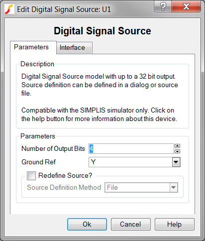
To configure the Digital Signal Source, double click on the symbol to open the parameter editing dialog:
| Label | Parameter Description |
Number of Output Bits |
Number of output bits for the digital signal source |
Ground Ref |
Determines whether or not a device has a ground
reference pin. |
Redefine Source? |
Determines whether the source is to be redefined after the dialog is closed.
|
Source Definition Method |
|
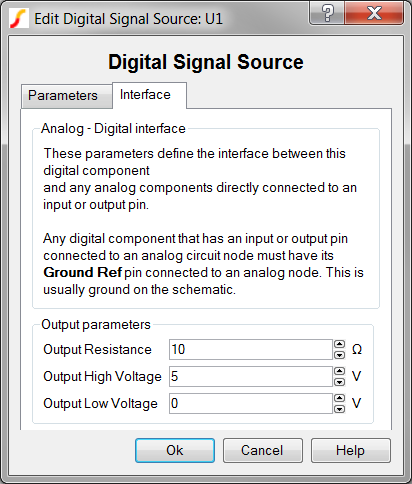
Clicking on the Interface tab displays the Analog - Digital interface parameters:
| Label | Parameter Description |
Output Resistance |
|
Output High Voltage |
|
Output Low Voltage |
The Digital Signal Source can be defined with a dialog, or with a points file.
Using the dialog method, the points definition is saved to a property on the Digital Signal Source symbol. This method is often used for small source definitions. You can define up to 255 logical input states with the dialog method.
To define the source with this method, check the Redefine Source? Checkbox and select dialog in the Source Definition Method box. After closing the main dialog, a table editing dialog will appear.
Using the file method, the points definition is saved as a plain ASCII text file, and before the simulation starts, the points file is read in and used to configure the source. This method is often used for large or complicated source definitions, although you can use this method for any size table.
The source used in the SIMPLIS
Lookup Table with Don't Care Input Definitions example is used to
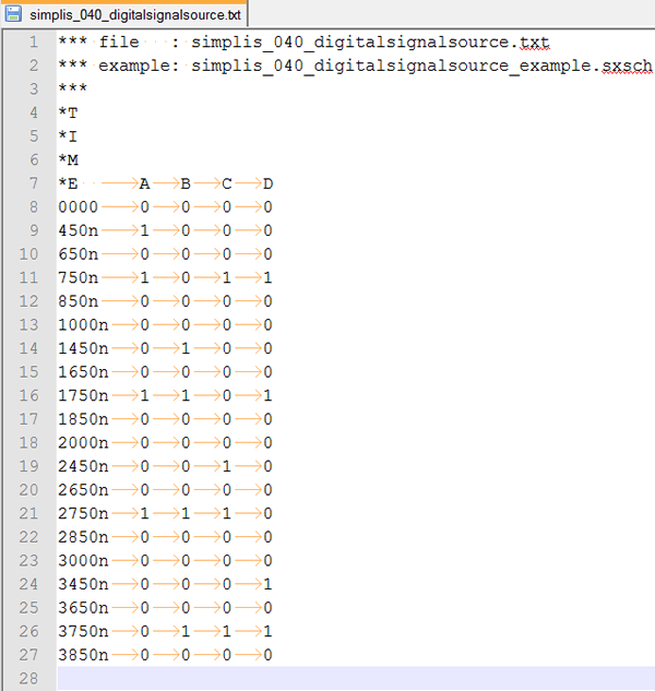
demonstrate the fie format. The file method uses whitespace, including
tabs and spaces to delimit columns in the points definition file. Lines
starting with the asterisk (*) are considered comments and are ignored.
The Time is defined in the first column. The states for each output pin
follow in MSB -> LSB order, and since these are single bits, the output
states are defined as either 0 or 1. The example table has five columns,
one for the time and four for the output bits.
Any number of points can be defined using the file method.
An example points definition file can be downloaded here : simplis_040_digitalsignalsource.txt. This file is also included in the zip archive of the example files simplis_040_digitalsignalsource_example.zip.
The file definitions for the Digital Signal Source and the Digital Lookup Tables are read into SIMPLIS by the same block of code. The errors in input file syntax are therefore similar. A description of the most common errors in input file formatting can be found here: Common File Formatting Issues
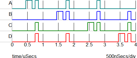
The test circuit used to generate the waveform examples in the next section can be downloaded here: simplis_040_digitalsignalsource_example.zip.
The waveforms below were taken from the state machine example described in the SIMPLIS Lookup Table with Don't Care Input Definitions.