Advanced SIMPLIS Training
Advanced SIMPLIS Training
|
To download the examples for Module 2, click Module_2_Examples.zip
In this Topic Hide
A number of factors which cause syntax or pre-process errors for a POP analysis.
How to properly setup a circuit for a SIMPLIS POP analysis.
There are several factors which will cause SIMPLIS to error out before or during a POP analysis. These errors are best learned through exercises and the order of the exercises reflects the usual order of errors a user would experience on a new design. Broadly speaking these errors fall into three categories:
Syntax and pre-process errors which halt the simulation before it starts
Schematic configuration errors
Actual POP convergence errors related to the circuit
The first error a user is likely to encounter occurs when a POP analysis is specified, but no TRIG_GATE parameter is defined. This commonly happens when a user opens the Choose Analysis dialog and selects the POP analysis check box but doesn't provide any Trigger gate information.
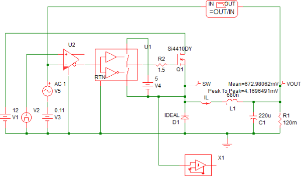
Open the schematic 2.8_POP_syntax_failures.sxsch.
Press F8 to open the Choose
SIMPLIS Analysis dialog.
Result: The Choose SIMPLIS Analysis dialog opens.
The POP analysis is specified, but neither the Use "POP Trigger" schematic device check box is checked nor is there a explicit literal
trigger gate defined in the Trigger
gate field on the dialog.
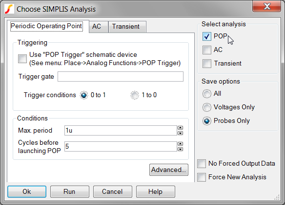
Click on the Run button
to run the simulation.
Result: The simulation halts with a syntax error.
The following message box opens:
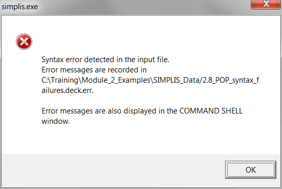
Click OK.
Result: the message box closes, and the syntax
error are output to the shell:
****************************************
<<<<<<<< Error Message ID: 1043 >>>>>>>>
input file C:\Training\ast_02\Module_2_Examples\SIMPLIS_Data/2.8_POP_syntax_failures.deck, line 3:
.POP TRIG_COND=0_TO_1 MAX_PERIOD=1u
A parameter specification in
one of the following four forms
TRIG_GATE=value
TRIG_GATE= value
TRIG_GATE =value
TRIG_GATE = value
is expected at the location where
`TRIG_COND' occupies.
This error occurs because the POP analysis is being run, and the .POP statement located in the command (F11) window is missing the TRIG_GATE parameter. This parameter is usually automatically added by the program when POP Trigger schematic device is used; however, in this exercise you have not told the program to look for the POP Trigger schematic device. In the next exercise you will tell the program to look for the POP Trigger schematic device.
In this exercise, the same circuit you used in the first example will be used. You will tell the program to use the POP Trigger schematic device; however, there is no POP Trigger device in the design. The program will generate a different error.
Open the schematic 2.8_POP_syntax_failures.sxsch.
Press F8 to open the Choose SIMPLIS Analysis dialog.
Check the Use POP Trigger schematic device check box. The configured
dialog will appear as follows:
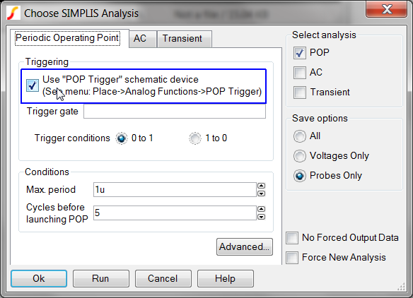
Click on the Run button
to run the simulation.
Result: The simulation halts with a syntax error.
The following message box opens:
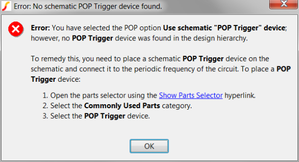
This error message communicates the steps required to remedy this error, that is, to add a POP Trigger schematic device to the design. In the next exercise, you will follow the error message instructions and add a POP Trigger schematic device.
In this exercise you will add the POP Trigger schematic device, and run the simulation.
Open the parts selector using the Show Parts Selector hyperlink.
Select the Commonly Used Parts category
Select the POP Trigger device.
Click on the Place POP Trigger hyperlink.
Move the mouse over to the wire connected to the SW node.
Click the mouse to place the POP
Trigger device.
Result: your schematic should appear as follows:
Run the simulation.
Results:
The POP simulation fails to converge because the maximum POP period is set to 1us, while the converter has a 2us period.
A transient simulation is launched for 100us, which is 100 times the maximum POP period parameter.
A error message is output to the SIMetrix/SIMPLIS command shell.
The error message which is generated is:
****************************************
<<<<<<<< Error Message ID: 5020 >>>>>>>>
Periodic Operating-Pt Analysis:
Reaching a time duration equal to
`2.00000e-006' without registering the
triggering condition that defines
the start of a period. Check your
circuit and/or initial conditions.
The error message in this exercise also occurs whenever the circuit stops switching for a time period greater than the Max. Period parameter. In this case, the circuit never switches at a period less than the Max. period parameter.
In the next exercise you will set the Maximum POP Period and successfully run the POP analysis.
Using the same schematic as you used in the previous example,
Press F8 to open the Choose SIMPLIS Analysis dialog.
Change the Max. Period
parameter to 2.1us. The configured dialog will appear as follows:
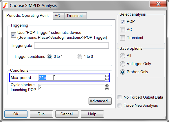
Run the simulation.
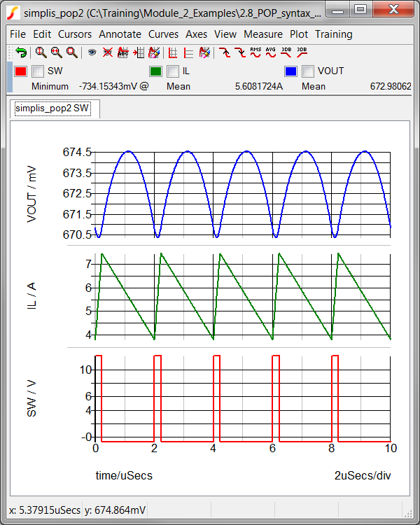
Result: The POP simulation converges and 5 cycles
of the POP waveforms are output to the graph viewer:
There are a number of POP syntax errors which cause a circuit which would otherwise successfully converge in a POP analysis to abort before the simulation starts.
© 2015 simplistechnologies.com | All Rights Reserved