Advanced SIMPLIS Training
Advanced SIMPLIS Training
|
To download the examples for Module 3, click Module_3_Examples.zip
In this Topic Hide
How the schematic netlisting process converts symbols into instantiation lines in the netlist.
How some models are generated on-the-fly during netlist generation with a script called a TEMPLATESCRIPT.
How the Netlist Preprocessor works to expand the capability of SIMPLIS
Most users would be hard pressed to answer the question posed in this lesson's title: What Happens When You Press F9? The answer in not a simple one, as the launching of a SIMPLIS simulation involves four major steps:
Netlist the schematic to convert symbols and wires into plain ASCII
text representations.
Resulting File: /SIMPLIS_Data/<design_name>.net.
Find POP Trigger device in hierarchy if a POP analysis is specified and the Use "POP Trigger" schematic device is checked in the Choose SIMPLIS analysis dialog.
Preprocess Netlist and POP Trigger gate information to create a
.deck file.
Resulting File: /SIMPLIS_Data/<design_name>.deck.
Syntax check the .deck file and run SIMPLIS on the .deck file.
On a schematic, the pins of various symbols are connected to each other by wiring "nets" or nodes. During the SIMPLIS netlisting process, each net is assigned a net (node) number. Within SIMPLIS, each net, or circuit node, must be represented by a positive integer, often called a node number. Any user-assigned node names will be automatically converted to node numbers during the SIMPLIS netlisting process. [Unlike SIMPLIS, SIMetrix Spice does not require the conversion of node names to node numbers.]
During schematic netlisting, an instantiation line is generated in the SIMPLIS netlist for each schematic symbol. This device instantiation line contains the reference designator of the symbol, an indicator of the electrical circuit model to be used, and a list of the nets to which each of the device pins are connected. This device instantiation line is typically a single line of ASCII text.
To define the precise syntax of each device instantiation line entry to the netlist, the netlisting program uses the SIMPLIS_TEMPLATE, or TEMPLATE properties, if they exist, or the MODEL, REF, and VALUE properties if there is no SIMPLIS_TEMPLATE or TEMPLATE property.
Some models are generated "on-the-fly" by a SIMetrix/SIMPLIS script. Symbols with a TEMPLATESCRIPT property have a model which is created by the template script at netlist time. In addition to generating the model, the TEMPLATESCRIPT also generates a new TEMPLATE or SIMPLIS_TEMPLATE property value.
The TEMPLATE <nodelist> keyword tells the netlister to include the nets connected to the symbol in the pin order specified by the symbol.
The text in the F11 Window is added to the beginning of the netlist.
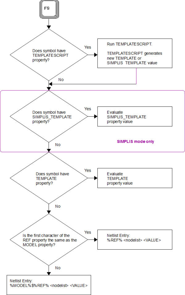
During the netlisting process, the netlister determines the netlist instantiation line for each symbol with the logic shown in the following flow chart. The values enclosed in percent signs, such as %REF% are literal substitutions, that is %REF% is the value of the REF property for the symbol. Special template keywords are enclosed in greater than and less than brackets <>, such as <nodelist>, which is a listing of all nodes connected to the symbol. Capitalized text in this flow chart represent symbol property names, such as TEMPLATE, SIMPLIS_TEMPLATE, REF, MODEL, etc.:
The netlist file is created by the netlister, and can be viewed with the SIMetrix/SIMPLIS Command Shell menu SIMPLIS Edit Netlist (before preprocess). The netlist at this stage is a raw collection of instantiations - that is, the connectivity of a number of symbols and the parameters associated with those symbols. Many of the electrical models are not present in the netlist at this point and the variable expressions have not been evaluated to numerical results either. Both of these operations are performed by the netlist preprocessor.
Open the schematic 3.1_SelfOscillatingConverter_POP.sxsch.
Run the simulation.
From the command shell menu, select SIMPLIS
Edit Netlist (before preprocess).
Result: The Netlist file opens in Notepad++:
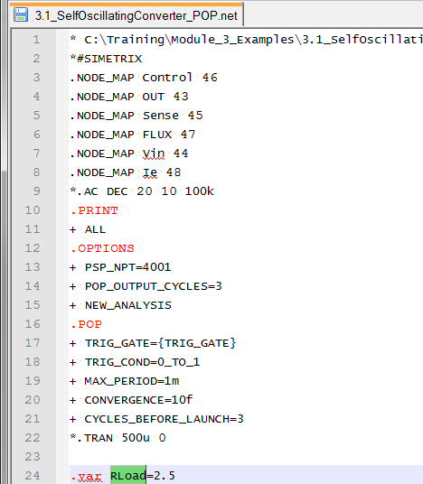
Note the RLoad variable statement highlighted on line 24 in the above image.
Double-click on the RLoad
variable on line 24 to highlighted it as above.
Result: All occurrences of RLoad are
highlighted in the document.
Scroll down through the netlist looking for the next occurrence
of the highlighted RLoad text.
This should occur on line 119 where the expression {RLoad}
is used for value of the load resistor R3.
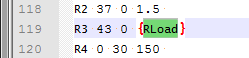
As you can see, at this point in the process, the netlist still contains the unevaluated variable expressions used in parameterization. These expresssions are evaluated, or resolved to numbers, by the netlist preprocessor.
The POP Trigger schematic device is a special symbol that SIMPLIS uses to identify the beginning of each switching period of the circuit. The program actually searches each level of the design hierarchy for the POP Trigger device. A script opens each schematic in a hidden mode, and interrogates the schematic, looking for POP Trigger devices. A list of locations and POP Trigger device references is collected and if there is only one POP Trigger present, the actual trigger gate is added as a .VAR statement when the netlist is preprocessed.
A great deal of "heavy lifting" is performed by the netlist preprocessor. This part of the SIMetrix/SIMPLIS program performs a number of tasks on the netlist file, and produces the SIMPLIS-ready deck file. The netlist preprocessor performs the following tasks:
Adds the text from any files defined with the .INCLUDE statement to the netlist. Electrical models stored in ASCII text files can be included in this manner.
Evaluate all expressions defined with curly braces {}.
Evaluate all .IF, .ELSE branches, and .WHILE loops.
If subcircuit models don't exist in the netlist or include files, the preprocessor searches the SIMetrix/SIMPLIS library system for the subcircuit definitions. Details are covered in 3.0.2 What Actual Device is Simulated in SIMPLIS?.
Flattens the deck so that every instance of every subcircuit has a unique reference designator.
Although the list of actions performed by the preprocessor is short, each action represents a powerful expansion of the capabilities of the program. For example, #3 listed above allows users to define models whose structure can be programmatically altered based on parameters the modeler defines. This model "creation" process happens every time SIMPLIS is executed, and is transparent to the user. The majority of the built-in SIMPLIS models exploit this feature. For example, the electrolytic capacitor model has optional ESR and ESL. These circuit elements are added to the model during the preprocess stage. In the 6.1.2 Constant Current Subcircuit topic, you will create your own models which exploit the preprocessor's ability to dynamically generate a model at run time.
The output of the netlist preprocessor is the deck file, and can be viewed with the SIMetrix/SIMPLIS Command Shell menu SIMPLIS Edit Netlist (after preprocess). In this next exercise you will repeat Exercise #1: Examine the Netlist, but see that the expression for RLoad has been evaluated to the numerical result of 2.5 Ohms.
From the command shell menu, select SIMPLIS
Edit Netlist (after preprocess).
Result: The deck file opens in Notepad++:
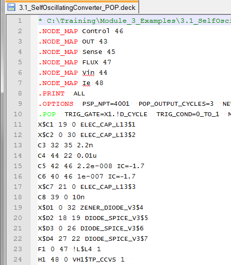
Notice there are no .VAR statements in the deck file.
Search for the text R3.
Use the shortcut key Ctrl+F to open the search dialog.
Type R3.
Click on the Find Next
button.
Result: The document scrolls to line
#106 where the first occurrence of the text R3 is located.:
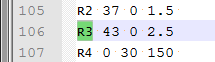
Notice the value of R3 is now 2.5.
The netlist preprocessor has evaluated all expressions in the netlist, pulled in all subcircuit definitions from the library and prepared the deck file for SIMPLIS to run. The next step passes the deck onto SIMPLIS where the deck file is checked for syntax errors before SIMPLIS executes the simulation. This is the step you are familiar with - this is when the SIMPLIS Status Window opens and the simulation starts.
In the next topic you will learn how parameters are passed into subcircuits and how the netlist preprocessor builds each subcircuit based on these parameters when the simulation is executed.
A number of SIMPLIS models are generated using templatescripts. These models include most of the Digital Libraries, except the gates and flip-flops. Creating models using a templatescript is covered in the Model_Generation_Using_TEMPLATESCRIPTS topic.
The procedure to run a design in SIMPLIS has four distinct steps:
© 2015 simplistechnologies.com | All Rights Reserved