Advanced SIMPLIS Training
Advanced SIMPLIS Training
|
To download the examples for Module 3, click Module_3_Examples.zip
In this Topic Hide
How the preprocessor copies subcircuit definitions from the global library to the deck file.
How parameters are passed into subcircuits.
How parameters are used to dynamically create the resulting subcircuit definitions.
How each subcircuit is made unique during netlist preprocessing.
The basics of the subcircuit interface.
In the previous topic, 3.0.1 What Happens When You Press F9?, you followed the process of netlist creation and netlist preprocessing to generate the final simulation deck file. In that topic you followed the expression {Rload} from symbol to netlist to the deck file where the expression {Rload} was evaluated and replaced with the numeric value 2.5.
In this topic you will learn how subcircuits can be defined in a library and how the netlist preprocessor copies these subcircuit definitions to the deck file. The netlist preprocessor searches the installed libraries for any subcircuit not already contained in the netlist, then copies the subcircuit definition from the library and inserts the definition into the deck file. Additionally, any parameters and expressions in the model definition are evaluated, resulting in the final model used in the simulation.
Almost all complex devices made up of more than a single primitive device are implemented as subcircuits. In this topic you will learn how subcircuits, when combined with parametrization, can be extremely powerful.
In this exercise you will follow the path of the electrolytic output capacitor C1 from schematic symbol to netlist to deck file definition. The electrolytic capacitor model is built-into SIMetrix/SIMPLIS as a subcircuit library device. The preprocessor will copy the definition of the electrolytic capacitor from the library, preprocess any .IF and .ELSE statements in the model, and evaluate any expressions. The resulting text entered into the deck will have purely numerical values.
Open the schematic 3.1_SelfOscillatingConverter_POP.sxsch.
To get started, select the first output capacitor C1,
and right click and execute the menu Edit/Add
Properties... or use the training keyboard shortcut
F3.
Result: The Edit Properties dialog for
C1 opens:
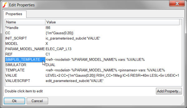
Because the model type is X,
this symbol calls a model defined as a subcircuit. In comparison,
a primitive capacitor in SIMPLIS has a MODEL property value of C. Because the symbol for C1 has
a SIMPLIS_TEMPLATE property, this property determines the syntax of
the netlist instantiation line for this device. The SIMPLIS_TEMPLATE
for the electrolytic capacitor is:
<ref> <nodelist> %PARAM_MODEL_NAME% vars: %VALUE%
From the command shell menu, select SIMPLIS
Edit Netlist (before preprocess).
Result: The Netlist file opens in Notepad++
Use the shortcut key Ctrl+F to open the search dialog.
Type C1.
Click on the Find
Next button.
Result: The document scrolls to line #40:

The netlist entry created by the SIMPLIS_TEMPLATE is called the instantiation, and this terminology
will be used throughout the rest of the course. The SIMPLIS_TEMPLATE
and the netlist instantiation for C1 has five distinct pieces, or
tokens. These tokens are:
SIMPLIS_TEMPLATE Token |
Netlist Value |
| <ref> | X$C1 |
| <nodelist> | 19 0 |
| %PARAM_MODEL_NAME% | ELEC_CAP_L13 |
| vars: | vars: |
| %VALUE% |
The instantiation for C1 defines a number of things:
Because the first character of the Reference designator is a X, this is a subcircuit.
The capacitor is connected between nodes 19 and 0. Node 0 is ground on the schematic.
The model used is called by name : ELEC_CAP_L13. This subcircut can be defined either in the netlist, the F11 window, an include file, in a local user library, or in this case, in a global SIMPLIS library.
The vars: keyword tells the netlist preprocessor to pre-process the subcircuit using the optional parameters after the vars: keyword.
The subcircuit has 7 parameters which are passed into the subcircuit
definition. These are the key-value pairs after the special vars: keyword:
| Parameter Name | Parameter Value |
| LEVEL | 2 |
| CC | 1m |
| RSH_CC | 1Meg |
| IC | 5 |
| RESR | 40m |
| LESL | 5n |
| USEIC | 1 |
A key concept to understand is that the instantiation only defines which model is used, it's connectivity, and the optional parameters used. The electrical model definition is stored in one of the locations listed in item 3 above.
At this point the only thing missing is the actual definition for the electrolytic capacitor. In the next exercise you will view the model for the subcircuit capacitor ELEC_CAP_L13.
On the 3.1_SelfOscillatingConverter_POP.sxsch schematic, select C1. The capacitor symbol should turn blue indicating the capacitor is selected.
Right click to bring up the context menu.
Select the special training menu item View
Model in Notepad++.
Result: The simplis_param.lb file opens
in Notepad++ to line 150 where the subcircuit is defined.
Scroll down so the entire model is visible:
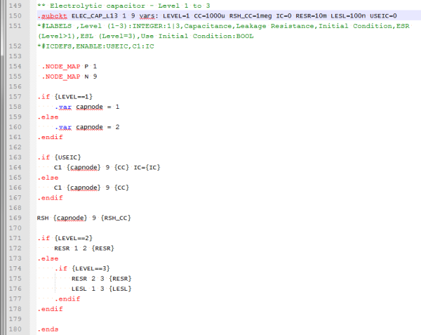
The lines from line number 150 to 180 define the electrolytic capacitor model used by the electrolytic capacitor symbols on this schematic. Note the distinction between a model and a symbol. The symbol creates a netlist instantiation line; the model is the electrical definition that is called by the instantiation. Every subcircuit definition in SIMPLIS begins with a .subckt statement, and ends with a .ends statement. As with everything in SIMetrix/SIMPLIS the program is not case sensitive.
The first line defines the "subcircuit interface", that is:
The subcircuit name
A list comprising the node number that each pin of this subcircuit is connected to
The default parameter values. Parameter values passed into the subcircuit on the netlist instantiation line over-ride the default parameters on the .subckt line.
Notice the subcircuit interface line is very similar to the instantiation line in the netlist entry for the device. A few very critical points need to be made.
|
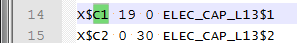
The netlist contains three electrolytic capacitor instantiations, with reference designators C1, C2, and C7. The two entries for C1 and C2 are:
Notice the two instantiation lines are nearly identical except the parameters and the connected node numbers. This is another critical concept:
| Multiple Instantiations in a netlist can call the same subcircuit; however, the resulting deck file entries will be different because the parameters passed on the instantiation line will likely be different for each instantiation. The netlist preprocessor uses the parameters which are passed to build a custom subcircuit for each instantiation. |
In the next exercise you will see how the netlist preprocessor creates custom subcircuits for C1 and C2.
From the command shell menu, select SIMPLIS
Edit Netlist (after preprocess).
Result: The deck file opens in Notepad++:
Use the shortcut key Ctrl+F to open the search dialog.
Type C1.
Click on the Find
Next button
Result: The deck file scrolls to line #14
where the instantiation line for C1
is located.
Note the difference between the netlist and deck file instantiations as shown in the table below:
| Netlist |
|
Deck |
|
The two differences are:
The deck entries have no parameters - the parameters have been passed into the subcircuit and evaluated, creating a custom subcircuit for C1 and C2.
The deck entries have a $1 and $2 appended to the subcircuit name - that is, two unique subcircuits have been created.
Next, let's look at the subcircuit definitions for the two subcircuits called by the deck instantiations for C1 and C2.
In the Notepad++ window, search for ELEC_CAP_L13$1.
Use the shortcut key Ctrl+F to open the search dialog.
Type ELEC_CAP_L13$1.
Click on the Find
Next button twice.
Result: The deck file scrolls to line
401 where the netlist preprocessor has placed the subcircuit for
C1:
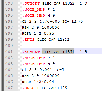
The capacitor C1 is a Level 2 capacitor - meaning the capacitor is a network of an ideal capacitor, a shunt resistance, and a series resistance. The parameters passed into the subcircuit are used to both determine the schematic configuration of the subcircuit capacitor, as well as to set the values for each circuit element. Note: Extra parameters can be passed into the subcircuit at the netlist stage. In this case, the LESL parameter is not used by the subcircuit after the preprocessor has been run, because there is logic contained in the model that keys off the value of the LEVEL parameter. This logic determined that the equivalent series inductor was not to be included in the final simulation deck file.
The subcircuit definition for the capacitor C2 immediately precedes the subcircuit for C1. Note the subcircuit contains the same devices, connected to the same subcircuit net numbers, but the circuit element values are different.
The following animated GIF image shows the netlist preprocessor as it steps through the model definition from the library, and generates the actual subcircuit. Note that the netlist preprocessor eliminates any blank lines and all comment lines which begin with an asterisk.
The netlist preprocessor copies subcircuit definitions from the global library to the deck file, then evaluates the parameters and conditional branches defined with the .IF and .ELSE statements.
© 2015 simplistechnologies.com | All Rights Reserved