Advanced SIMPLIS Training
Advanced SIMPLIS Training
|
To download the examples for Module 5, click Module_5_Examples.zip
In this Topic Hide
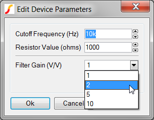
In this topic you will add a basic parameter-editing dialog to the parameterized RC filter schematic component symbol. Consider the following dialog configured to edit the three parameters used in the parameterized RC filter subcircuit:
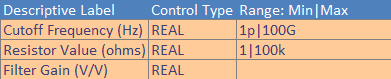
To define each parameter-editing control, three data elements are required: Descriptive Label, Type, and Range. The following table describes these elements in detail.
| Data Element | Example Data Value | Description | ||||||||||||||||||
| Descriptive Label | Cutoff Frequency (Hz) | Any text string which does not
contain the colon or comma characters. The descriptive
label is compliant with basic HTML markup, which means that you
can do the following:
|
||||||||||||||||||
| Type | REAL | Five types of parameter-editing controls are allowed with NewValueDialog function. The most common types are the Real and Integer spinner controls, followed by the List and Boolean types. The String entry type can be used to prompt the user for general string information and is used infrequently. The five types are described in the table below:
|
||||||||||||||||||
| Range | 1p|100G | The range field is used for the Real, Integer and List controls and is ignored for other types. The range field for the Real and Integer control types contains the minimum and maximum values separated by the pipe "|" character. In this example, 1p is the minimum value and 100G is the maximum value. Engineering suffixes are permitted.
|
In SIMetrix/SIMPLIS, the three data fields for each control are concatenated
into a string using the colon character as a delimiter. For example, the
three data elements for the Cutoff Frequency
parameter control are concatenated into the following string with the
colons in red:
Cutoff Frequency (Hz):REAL:1p|100G
This string is a complete parameter-editing control definition for a single parameter. Multiple parameter-editing control definitions are further concatenated to create a single string to define the set of parameter-editing controls for a dialog.
Each parameter-editing control definition is then concatenated into
a single string using the comma character as a delimiter. In this example,
there are three parameter-editing controls, and the concatenated string
of parameter-editing control definitions is shown below with the commas
in red:
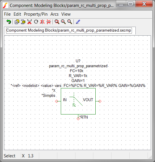
The actual parameter-editing functionality is provided by a script. In topic 4.0 What is a Symbol? you learned that the VALUESCRIPT symbol property holds the script name which is executed when you double click on the symbol. SIMetrix/SIMPLIS includes parameter-editing valuescripts that are specialized for the combination of each dialog definition (NewValueDialog or TabValueDialog) with each parameterization method (Single-Property or Multi-Property).
All valuescripts read the symbol or subcircuit definition for the dialog definition and then present the user with the dialog for editing. In this section, you will store the dialog definition on three Reserved_Symbol_Properties.
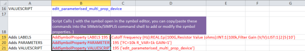
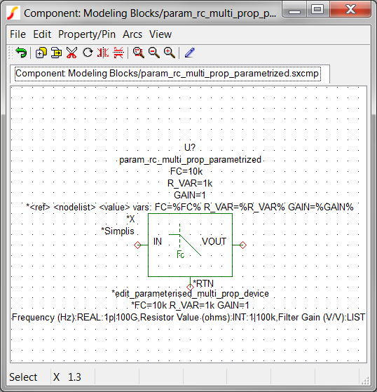
All parameter-editing dialogs use the LABELS symbol property to store the parameter-editing control information. The following string defines the LABELS property for the parameter-editing dialog shown below:
Cutoff Frequency (Hz):REAL:1p|100G,Resistor Value (ohms):INT:1|100k,Filter Gain (V/V):LIST:1|2|5|10
The PARAMETERS symbol property holds the parameter names and their default values in a parameter string. In this example, the PARAMETERS property is:
FC=10k R_VAR=1k GAIN=1
| CAUTION: The parameter names in the PARAMETERS symbol property must be in the same order as the parameter-editing control definitions stored in the LABELS symbol property. |
The VALUESCRIPT symbol property holds the script name to execute when a user double clicks on the symbol. This example uses the Multi-Property_Method, which requires the multi-property valuescript:
edit_parameterised_multi_prop_device
Although the amount of data required to define a parameter-editing dialog is reasonable, the syntax is exacting. For this reason, a spreadsheet tool has been created to help define dialog parameter-editing controls. This spreadsheet, 5.3_new_value_dialog_definition_worksheet.xlsx, is included with the Module 5, in the Module_5_Examples.zip file.
In the next exercise, you will add the dialog definition described in this topic to the multi-property parameterized RC filter symbol using the spreadsheet.
Open the spreadsheet 5.3_new_value_dialog_definition_worksheet.xlsx located in the C:\Training\Module_5_Examples directory.
Note the following formats:

Note the content of the various columns and rows:
Instead of adding individual symbol properties in this exercise, you will copy a set of script commands from the spreadsheet and execute the commands in SIMetrix/SIMPLIS.
Open the schematic 5.5_parametrized_rc_filters_multi_prop_dialogs.sxsch.
To add the parameter-editing control definitions to the symbol for the parameterized RC filter, follow these steps:
On the SIMetrix/SIMPLIS schematic, select the symbol for U2.
To open the schematic component in the Symbol Editor, type
the training keyboard shortcut Shift+S,
or right click and select Edit
Symbol....
Result: The symbol opens in the Symbol
Editor.
Navigate to the spreadsheet window, and select the red
text in cells B19, B20, and B21.
Result: The selected cells should appear
as follows:
Press Ctrl+C to
copy the cells to the windows clipboard.
Result: The selected cells have an
animated border indicating the cells are selected.
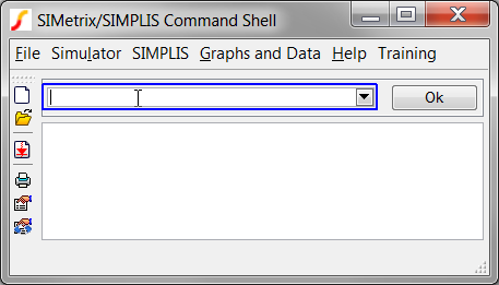
Navigate to the SIMetrix/SIMPLIS command shell window.
Click the mouse in the command line entry located at the
top of the command shell window:
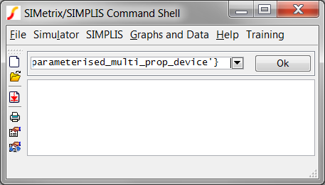
Press Ctrl+V to
paste the commands in the command line.
Result: The last part of the command
string is visible in the command line:
Press Enter, or
click Ok on the command
line.
Result: The commands are executed in
SIMetrix/SIMPLIS. Each AddSymbolProperty command adds a single
symbol property to the symbol. The commands apply the Hidden and
Protected property flags and add the properties below the symbol.
From the Symbol Editor menu, select File Save..., and then click Ok on the Save Symbol dialog.
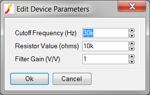
Navigate to the Schematic Editor window. Double click on U2, which is the RC filter attached
to the multi-prop(30kHz) probe.
Result: The parameter-editing dialog appears:
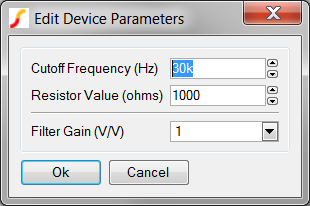
Change the Resistor Value 10k.
Click Ok to save your
changes.
Result: The parameter value for R_VAR changes
to 10000 on the symbol.
Note: The parameter-editing control for the resistor value is currently an integer type control, which returns numbers in non-engineering notation.
In the previous exercise you added the parameter-editing definition saved in the spreadsheet. This definition used three control types as a demonstration; however, the parameters being edited should be REAL types. In this exercise you will modify the dialog definition to use the REAL type control for all parameters.
Navigate to the spreadsheet window.
Modify cells F9 and F10 to be REAL. Note that the spreadsheet only allows the values you can select in the drop-down list.
Delete the Range entry for the Gain parameter in cell G10. This will allow any gain, including
negative gain to be input into the parameter-editing control.
Result: The changed cells in the spreadsheet appear as follows:
As in the previous example, copy the red script commands in cells B19, B20, and B21, and execute the commands at the SIMetrix/SIMPLIS command line.
Note:You must have the symbol editor open and the parameterized RC filter symbol loaded before executing these commands.
From the Symbol Editor menu, select File Save..., and then click Ok on the Save Symbol dialog.
Double click on U2,
the RC Filter symbol.
Result: The modified dialog appears. Each control type is
a Real type, and any gain value, positive or negative can be input
into the Filter Gain control. The resistor value is now presented
in engineering notation.
Click Ok.
Result: The R_VAR value on the schematic changes
to 10k, which is the return value for the REAL parameter-editing control.
One of the most common problems with dialog definitions occurs when the parameter control definition order in the LABELS property is different than the order in the PARAMETERS property. The program expects these two "arrays" to be in the same order.
If your symbol is missing one of the LABELS or PARAMETERS properties, the program produces an error in the command shell. All three special symbol properties must be present for the dialog to function properly.
At times, parameter-editing dialogs have been added to symbols without any parameters being passed to the subcircuit. In 5.1 Passing Parameters Into Subcircuits Using The SIMPLIS_TEMPLATE Property, you learned that parameters are passed to the subcircuit using the SIMPLIS_TEMPLATE property. It is entirely possible to add a dialog that functions properly, allowing edits to the appropriate symbol properties, but the symbol does not pass these properties to the subcircuit. It is important to remember that passing parameters through the symbol-to-subcircuit interface is different than editing the symbol properties.
It is possible to have valid LABELS and PARAMETERS symbol properties but the critical VALUESCRIPT property was not added.
Accidental new line characters in the LABELS or PARAMETERS definitions can cause "mysterious" errors.
© 2015 simplistechnologies.com | All Rights Reserved


