Advanced SIMPLIS Training
Advanced SIMPLIS Training
|
To download the examples for Module 4, click Module_4_Examples.zip
In this Topic Hide
Symbols have three primary functions:
Symbols define connectivity, and ideally the graphical symbol represents the underlying functionality of the electrical model.
Symbols may pass parameters to the underlying electrical model.
Symbols may have parameter editing dialogs which allow users to edit the parameters for the device.
Some common misconceptions about symbols:
Symbols are not models and vice-versa.
Symbols might not represent what you think - the electrical model can be subtly or dramatically different than the graphical depiction.
A few details for working with symbols:
Symbols may be stored in several locations, including a symbol library, on a schematic, or as a script file.
How to install and remove symbol libraries.
How to edit symbols.
The special symbol properties which determine the netlist content and other functionality.
Symbols and Models are often confused. In this topic you will learn the ins and outs of symbols, what symbols do in SIMetrix/SIMPLIS, and how to manage symbols.
The primary purpose of symbols is to connect models to wires, which, in turn, connect to other symbols. A good model designer would also design the graphical representation of the symbol to depict the underlying electrical model. While this seems obvious, consider a common item in power electronics - the capacitor. Capacitors often include equivalent series resistance and equivalent series inductance, yet the graphical representation of the capacitor symbol is often no different than the primitive capacitor which models a pure capacitance. Because symbols primarily define connectivity, and a capacitor is a two terminal device, a common symbol is often used. This often, and rightfully, confuses users. In section 3.0.2 What Actual Device is Simulated in SIMPLIS? you learned how to find exactly what device model is used in the simulation.
In the first exercise you will learn how symbols can call models which are quite different than the graphical symbol depicts.
Open the schematic 4.1_symbols_may_not_represent_what_you_think.sxsch.
Press F9 to run the simulation.
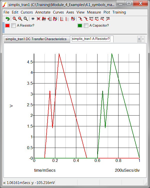
Result: The transient simulation executes
and the waveforms for the resistor and capacitor voltages are shown.
Clearly these voltages are not those of a resistor or a capacitor!
Extreme examples? Yes of course these are extreme examples. The point is that symbols and the models which they actually call, or otherwise put in the netlist don't have to correlate. In this example, two different methods were used to generate the resistor and capacitor models:
The model used by the resistor symbol is generated with a templatescript: 4.1_make_phony_resistor.sxscr.
The model used by the capacitor symbol is stored in a model library: 4.1_myCapacitor_model.lb.
Both files are located in the Module_4_Examples directory. The changes to the symbols are:
For the resistor symbol, a TEMPLATESCRIPT property is added, with the property value: 4.1_make_phony_resistor.sxscr. When the netlist is created, the templatescript 4.1_make_phony_resistor.sxscr is called, the script then modifies the SIMPLIS_TEMPLATE property value. The templatescript replaces the resistor model with a PWL voltage source.
The capacitor symbol has two modifications:
How these models are created or included in the simulation deck will be discussed in section 4.1 What is a Model?
Two graph tabs were generated from the design simulated in Exercise_#1:_Symbols_May_Not_Represent_What_You_Think! The first graph tab has the DC transfer characteristics of a user-defined diode. In the following exercise, you will learn more about user-defined diodes and how these diodes might not conform to the graphical representation of a diode symbol.
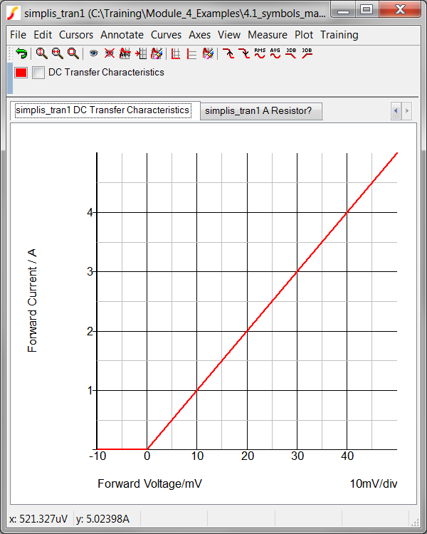
Select the first tab with the title
simplis_tran1 DC Transfer Characteristics.
Result: The DC Transfer Characteristics
of the user-defined diode are displayed on the graph viewer. Note
that the model is resistive, with a zero volt forward drop and a 10mΩ
forward resistance.:
Now double click on the diode symbol to view the User-defined
diode properties:
Result: The Edit Diode : D1 Parameters
dialog opens.
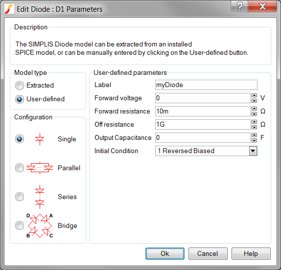
We have all been trained that all diodes have some finite, positive forward voltage drop. Mentally, a user sees the diode symbol and thinks "diodes have a forward drop and an exponential forward transfer characteristic." This example circuit was purposefully designed to show that user-defined diodes can have a zero-volt forward drop. Why would you want to have a zero-volt forward drop? Because this user-defined diode makes an ideal synchronous rectifier, which behaves just like a MOSFET with the "perfect" gate drive timing waveforms. Whenever the circuit connected to the diode attempts to force forward current through the diode, the diode behaves like a 10mΩ resistor. When the diode is in a blocking state, the resistance is 1GΩ.
All semiconductor symbols used in SIMPLIS schematics call a electrical model which has PWL transfer characteristics. The model parameter extraction algorithms execute SIMetrix SPICE simulations on the SPICE model and curve fit a PWL model to the SPICE simulation curves. In contrast to the user-defined model in this exercise, a parameter extracted diode would have a forward voltage drop and three PWL segments, as opposed to the two segment model used in the user-defined diodes.
Symbols are not models and models are not symbols. At SIMPLIS, we often hear users say "I placed this model on the schematic." In 99% of the cases this is not true, as the getting started example demonstrated. You place symbols on the schematic and those symbols call electrical models, defined as a Schematic Component, as a ASCII text model from a library file, or defined with a script. Compared to models, symbols have a rather simple job to accomplish - to interconnect other symbols and as you will see, to pass parameters to the underlying electrical model.
In section 3.0.2 What Actual Device is Simulated in SIMPLIS?, you learned how parameters stored on a symbol property were passed through to the electrical model using the SIMPLIS_TEMPLATE property. In the 5.1 Passing Parameters into Subcircuits Using the SIMPLIS_TEMPLATE Property topic, you will learn how to pass parameters to a subcircuit model. At this point, just remember that symbol properties store model parameters. Those symbol properties are passed to the model as model parameters via the SIMPLIS_TEMPLATE property.
The VALUESCRIPT and PARAMSCRIPT properties define the scripts which are called when a user interacts with the symbol. The VALUESCRIPT is called when the user double clicks on the symbol. If the user right clicks and executes the Edit Additional Properties... context menu, the PARAMSCRIPT is called. Adding parameter editing dialogs is covered in the 5.2 Parameter-Editing Dialogs topic.
Symbols can be stored in several locations:
In a symbol library file - this is how most internal symbols are stored. Symbol library files are plain ASCII text files and have the file extension .sxslb.
As part of a Schematic Component file. A schematic component file includes both the symbol and the model in a schematic form. Schematic component files have the extension .sxcmp.
Locally on a schematic. Symbols stored locally cannot be used in other schematics. You can always copy local symbols from schematic to schematic if need be.
As a script. Several internal symbols are dynamically generated when placed on the schematic. This implementation is used when the symbol has a variable number of pins and storing individual symbols for all logical combinations would be difficult. A few examples include SIMPLIS digital devices, bus rippers, and jumper symbols.
When you place a symbol on the schematic, a copy of the library version is created and saved to the schematic file. This copy is called the instantiation and now resides in the schematic file. Because the symbols are copied to the schematic file, you can share a design with a colleague by sharing the schematic file alone. You can also add, modify, and delete symbol properties on the instantiated symbol without modifying the library version. This is important because the values for many symbol properties will be different than the default values saved in the library copy of the symbol. Consider the case of a large converter which might have 25 resistors, all with different values. The library version of the resistor symbol will have the default value of 1k, while each instantiation will have it's own local value for the resistance.
Symbols placed for hierarchical Schematic Component Files are treated differently. These symbols are read from the schematic component file and placed on the schematic. No local copy is saved.
There are several methods to edit a symbol. Probably the easiest is to use the context menu on the instantiated version of the symbol on a schematic. In the next exercise you will edit the Electrolytic Capacitor symbol and save it to a new symbol library.
Open the schematic 4.2_LLC_Closed_loop.sxsch.
Locate the output capacitor Co.
Select the output capacitor Co
and right click to display the context menu.
Result: The context menu appears with the
disabled menu options grayed out.
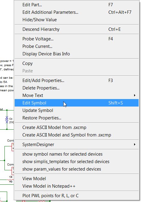
Select the menu item Edit Symbol.
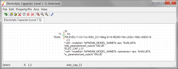
Result: The built-in Electrolytic Capacitor
(Level 1-3) symbol is opened in the Symbol Editor window:
Resize the symbol editor window to fill most of your screen. This will give you higher resolution for the next steps.
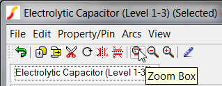
Click on the Zoom Box
tool bar button:
Zoom in on the capacitor symbol:
Locate the mouse cursor at the upper left hand corner of the capacitor symbol.
Press and hold the left mouse button while dragging the
mouse to the lower right hand side of the symbol to define a box.
Release the mouse button.
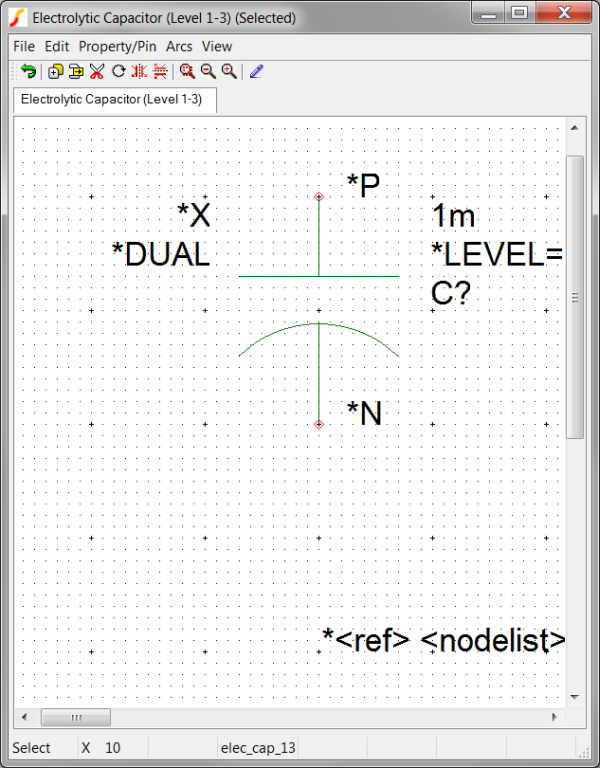
Result: The zoom factor increases to
display the graphical elements of the symbol in green and the
pins in red.
Add a "+" sign to the positive plate of the capacitor:
Click on the Wire Mode
tool bar button:
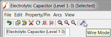
Add a graphical "+" using the wire mode. In this exercise, the exact location and size of the cross is irrelevant.
To start a segment, press the left mouse button,
To add another point, in this case, the end point, press the left mouse button again.
To cancel the current wire, press the right mouse button.
To exit the wire mode, press the Esc
key.
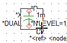
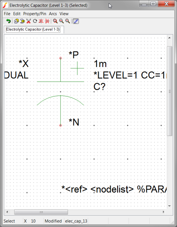
Result: The new electrolytic capacitor
symbol should appear approximately as follows. Don't sweat
the details - this can all be changed later.:
You are now ready to save the symbol. In this exercise you will save the symbol to a symbol library in the schematic's root directory.
Press the training shortcut key Ctrl+S
or execute the symbol editor File
Save menu item.
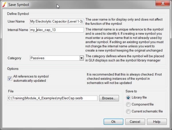
Result: The Save Symbol dialog opens:

You will save the modified symbol to a new symbol library and change the Internal Name so there is no conflict with the internal symbol.
Change the User Name from Electrolytic Capacitor (Level 1-3) to My Electrolytic Capacitor (Level 1-3).
Change the Internal Name from elec_cap_13 to my_elec_cap_13.
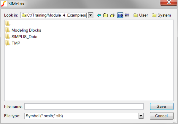
Click on the Browse...
button to navigate to C:/Training/Module_4_Examples/
Result: The dialog should appear
as follows, with the path C:/Training/Module_4_Examples/:
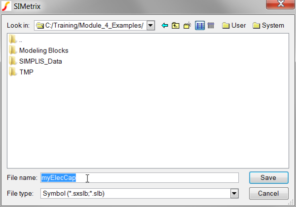
In the File
name box, type the model filename: myElecCap.
Result: The dialog should appear
as follows, both the path and file name have been filled in.
Click Save.
Result: The Save Symbol dialog
now has the full file path to the symbol library file:
Click Ok.
Result: The symbol is saved to
the library file. The program then prompts for you to install
the symbol library file:
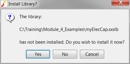
Click Yes on
the dialog to install the Symbol Library.
Result: A message appears in the
SIMetrix/SIMPLIS command shell:
Use Q to place new component
Select the schematic editor window.
Press Q to place
the new capacitor symbol.
Result: mouse cursor changes to
the capacitor symbol and after pressing the left mouse button,
the capacitor is instantiated on the schematic. Note the graphical
cross indicating the positive terminal of the capacitor is
visible.

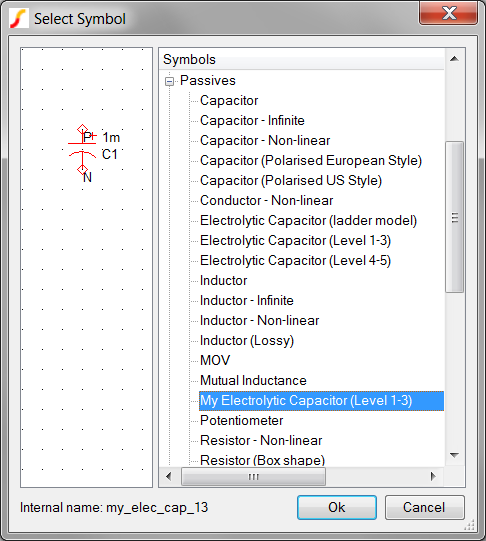
You can also place the newly created symbol from the symbol library.
Executing the schematic menu Place From Symbol Library... will open
the dialog. In the image below, the Passives
category has been opened, and as expected, the edited capacitor is located
in this category.
After saving the modified Electrolytic Capacitor Symbol to the symbol library, the program prompted you to install the library. A list of installed libraries can be found by opening the Symbol Manager. The SIMetrix/SIMPLIS command shell menu : File Symbol Editor ▶ Symbol Manager... opens the following dialog:
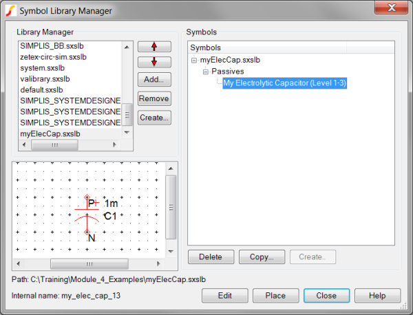
With this dialog, you can determine which libraries contain which symbols and add, remove, or create symbol libraries. The Help button links to a comprehensive help topic on the use of the Symbol Manager.
You can also install symbol libraries by the "drag-and-drop" method. Simply open a Windows Explorer window to the location of the symbol library file, and drag-and-drop the file to the SIMetrix/SIMPLIS command shell window. No message is given after you drop the symbol library file, the symbol library is installed quietly. You can always check the installed symbol libraries with the Symbol Manager.
The netlisting process was described in section 3.0.1 What Happens When You Press F9?. In that topic, the REF, MODEL, TEMPLATE and SIMPLIS_TEMPLATE properties were covered in some detail. The SIMPLIS_TEMPLATE property was covered in detail in the 3.0.2 What Actual Device is Simulated in SIMPLIS? topic. Several other special symbol properties exist:
| Symbol Property Name | Function |
| VALUESCRIPT | The script name which is called when a user double clicks on the symbol or presses F7. This usually opens a dialog to edit parameter values. The parameter values are saved to the symbol as symbol properties. |
| PARAMSCRIPT | The script name which is called when the user right clicks and executes the Edit Additional Parameters... context menu option or presses the keyboard shortcut Ctrl+Alt+F7. |
| TEMPLATESCRIPT | Defines the script name to be executed to modify the symbol template value during netlist generation. |
| INITSCRIPT | The script name used to back annotate the initial conditions for this symbol. |
| PARAMS | Passes parameters to the subcircuit. This is the shortcut method and is not the preferred method. |
| LABELS | Reserved for parameter editing dialogs. |
| PARAMETERS | Reserved for parameter editing dialogs. |
| TABS | Reserved for parameter editing dialogs. |
| GROUPS | Reserved for parameter editing dialogs. |
| DESCRIPTIONS | Reserved for parameter editing dialogs. |
| SIMULATOR | Determines the symbol's compatibility with the SIMetrix or SIMPLIS simulators. |
| schematic_path | The full or relative path to the underlying schematic. Used for Schematic Component files. |
You should avoid using the special symbol properties for purposes other than their designated function. A full listing of special symbol properties can be found in the User's manual at: What is a Property?
© 2015 simplistechnologies.com | All Rights Reserved