Advanced SIMPLIS Training
Advanced SIMPLIS Training
|
To download the examples for Module 3, click Module_3_Examples.zip
In this Topic Hide
How to use a schematic as a "template" which is loaded with component values from a Load Component Values configuration file.
The format of the Load Component Values configuration file.
How to auto-generate a Load Component Values configuration file from a schematic.
How to load a configuration file from a SIMetrix command line.
How to load a configuration file from a SIMetrix script.
Close the Graph viewer and the schematic 3.1_SelfOscillatingConverter_POP.sxsch, if its open.
Re-open the schematic 3.1_SelfOscillatingConverter_POP.sxsch.
Run the simulation.
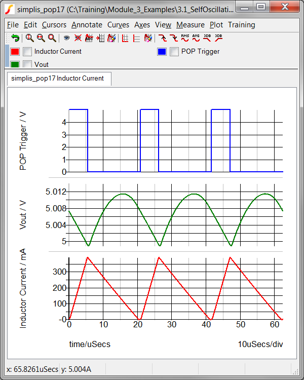
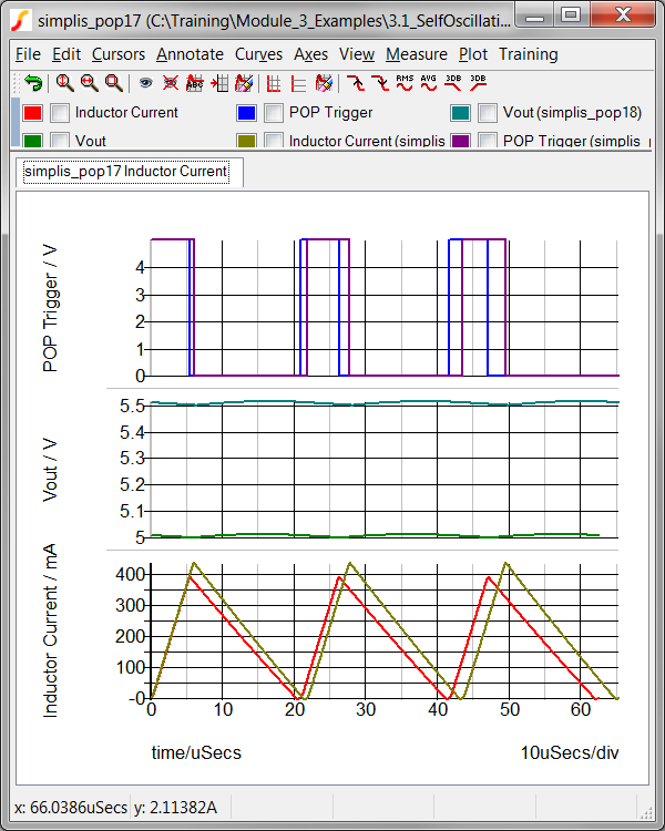
Result: The converter simulates as before,
with the nominal output voltage of 5.0V. The graph viewer displays
the 3 curves for the POP Trigger, Vout and Inductor Current.
From the schematic menu, select Tools
Load Component Values Select a File to Load...
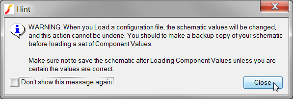
Result: A Hint message warns you that you
are about to change the schematic values, Click Close on this
dialog.
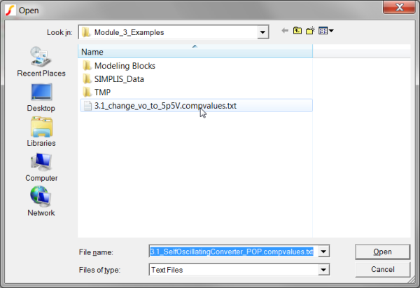
Result: A file selection dialog opens in
the schematic directory. The File
name field is populated with the default
configuration file name.
Select the only Load Component Values configuration file with
the file name: 3.1_change_vo_to_5p5V.compvalues.txt.
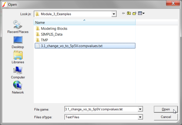
Click on the Open button.
Result: Individual values on schematic
symbols are edited by the Load Component Values feature. The changed
values:
Use Monte Carlo distributions for the input source, V1, and the feedback resistors R6 and R7.
Set the nominal output voltage to 5.5V.
Increase the saturation currents on the Magnetizing inductor L4 by 10%.
Run the simulation.
Result: The converter simulates as before,
but with the nominal output voltage of 5.5V. The graph viewer displays
3 new curves for the POP Trigger, Vout and Inductor Current, as well
as the original curves.
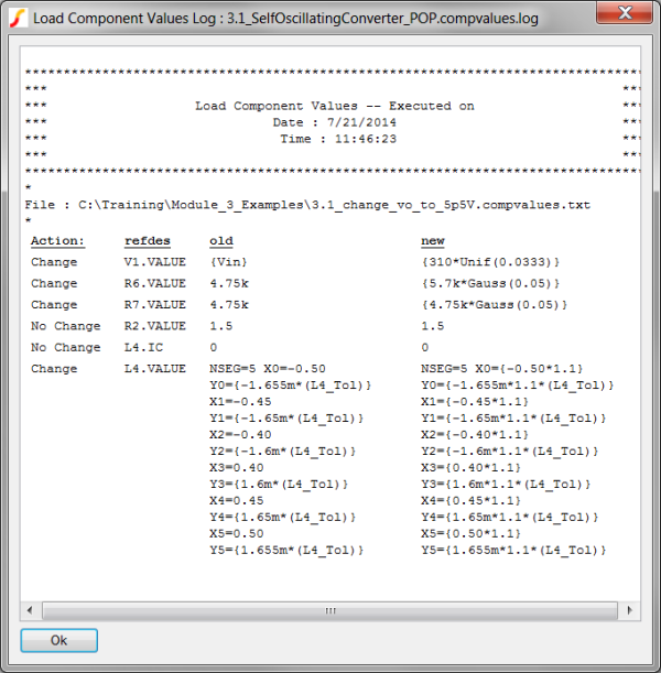
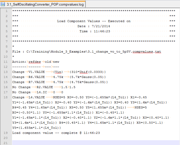
In the Getting Started section you loaded a schematic with new component values. The new values change the output voltage set-point of the converter to 5.5V and also increase the saturation currents for the PWL inductor L4. At the same time, the Monte Carlo distribution functions were added to the input source and voltage feedback resistors. After the component values were changed, the program reported a log to the SIMetrix/SIMPLIS command shell window, with the details of each change:
Load component value -- Started @ 11:46:23
Action: refdes old new
------- ------ --- ---
Change V1.VALUE {Vin} {310*Unif(0.0333)}
Change R6.VALUE 4.75k {5.7k*Gauss(0.05)}
Change R7.VALUE 4.75k {4.75k*Gauss(0.05)}
No Change R2.VALUE 1.5 1.5
No Change L4.IC 0 0
Change L4.VALUE NSEG=5 X0=-0.50 Y0={-1.655m*(L4_Tol)} X1=-0.45 Y1={-1.65m*(L4_Tol)} X2=-0.40 Y2={-1.6m*(L4_Tol)} X3=0.40 Y3={1.6m*(L4_Tol)} X4=0.45 Y4={1.65m*(L4_Tol)} X5=0.50 Y5={1.655m*(L4_Tol)} NSEG=5 X0={-0.50*1.1} Y0={-1.655m*1.1*(L4_Tol)} X1={-0.45*1.1} Y1={-1.65m*1.1*(L4_Tol)} X2={-0.40*1.1} Y2={-1.6m*1.1*(L4_Tol)} X3={0.40*1.1} Y3={1.6m*1.1*(L4_Tol)} X4={0.45*1.1} Y4={1.65m*1.1*(L4_Tol)} X5={0.50*1.1} Y5={1.655m*1.1*(L4_Tol)}
Load component value -- complete @ 11:46:23
In addition to reporting to the command shell, the log is saved as a file. The log can be viewed with the menu item: Tools Load Component Values View Log File.
SIMetrix/SIMPLIS has a built-in HTML viewer which can be used to view the log file. In this exercise you will view the log file using the HTML viewer.
From the schematic menu, select Tools
Load Component Values View Log File.
Result: The ASCII text log file is read
from disk, parsed into a HTML table, and displayed in a HTML viewer
dialog window. Because the values are formatted into a table, the
changes are readily apparent.
Resize the window to be wider or narrower - you should see the column data stretch or wrap to fill the available column width.
The log file is a plain ASCII text file located in the same directory as the schematic. The log file is automatically created every time the schematic is loaded with a configuration file and has the same name as the schematic but with the extension: .compvalues.log. In this exercise, you will open the log file in Notepad++.
Right click on the schematic tab:
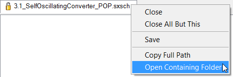
Select the Open Containing
Folder menu option.
Result: a Windows Explorer window opens
to the schematic directory.
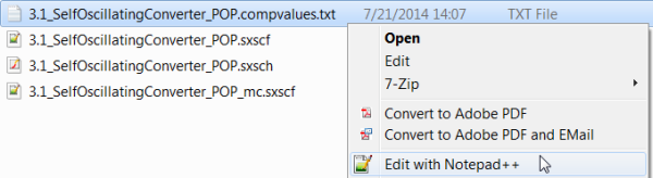
Open the 3.1_SelfOscillatingConverter_POP.compvalues.log
file in Notepad++ using the context menu:
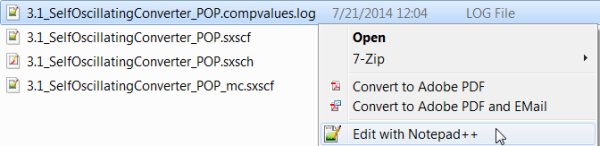
Result: The 3.1_SelfOscillatingConverter_POP.compvalues.log
file opens in Notepad++.
The Load Component Values configuration file can be created by hand, by another program or script, or by SIMetrix/SIMPLIS. The schematic menu: Tools Load Component Values Create Config File From Schematic... reads each symbol property, determines if that symbol property is compatible with Load Component Values, and saves the address-value pair to a configuration file.
In this exercise you will save a configuration file for the schematic to the default file name.
From the schematic menu, select Tools
Load Component Values Create Config File From Schematic...
Result: A file selection dialog appears,
prompting you for a file name to save the configuration file:
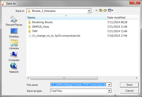
Click Save on the dialog.
Result: The program reads the top level
schematic and saves the configuration file. A message is output to
the SIMetrix/SIMPLIS command shell:
Created configuration file : C:\Training\Module_3_Examples\3.1_SelfOscillatingConverter_POP.compvalues.txt
The configuration file is a plain ASCII text file with two columns separated by a tab character. Following are the rules for the configuration file:
ADDRESS |
VALUE |
L1.DCR |
5m |
Note: The correct ADDRESS for any given parameter depends heavily on the type of symbol that is being used, not merely the type of component. The program supports many standard symbols, but custom or seldom-used symbols may require some tweaking in order to get the desired behavior. ADDRESS and VALUE must be separated by tabs.
As mentioned in the Configuration_File_Format section, the configuration file is a plain ASCII text file. As such, it can be viewed and edited in any text editor such as Notepad++.
Right click on the schematic tab:
Select the Open Containing
Folder menu option.
Result: a Windows Explorer window opens
to the schematic directory.
Open the 3.1_SelfOscillatingConverter_POP.compvalues.txt
file in Notepad++ using the context menu
Result: The Configuration file opens in
Notepad++:
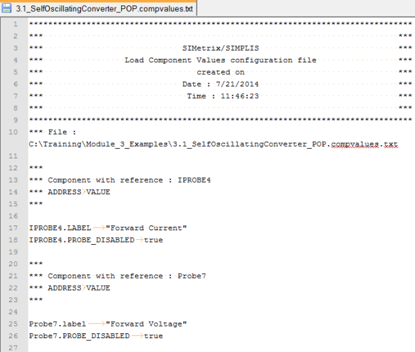
At this point you have the default configuration file open in Notepad++. In the screenshot shown above, the values for two components, IPROBE4 and Probe7 are shown. The configuration file can be edited to change values or to eliminate unneeded components.
A special switch /l
( the letter l, not the numeral 1) has been added to SIMetris/SIMPLIS
to automatically open a schematic and load a set of component values when
the program starts. The syntax for the command line switch is:
<full_path_to_simetrix.exe>
<full_path_to_schematic_to_open> /l <full_path_to_comp_values_file>
Note each of the three command line arguments are full paths.
The load component values feature is provided by the script load_comp_values.sxscr. The script has one optional argument -- a filename. Without the optional argument, the script attempts to load the default file, which is <schematic_name>.compvalues.txt. If that file cannot be found or cannot be opened, a file selection dialog opens to allow you to select a configuration file.
The load component values script can be called from any SIMetrix Script.
Schematics can be viewed as "templates" which contain the following information:
Connectivity between symbols.
Component values which can easily be changed with Load Component Values.
Analysis directives which are stored in the command (F11) window.
The Load Component Values configuration file is a simple text file where each line contains a single component address and its corresponding value. Each component address is separated from its value by the tab character.
Load Component Value configuration files can be created from the schematic and edited as needed.
Using the command line switch /l, you can open a schematic and load a set of component values.
Please fill out the Module # 3 Evaluation form at surveymonkey.com.
© 2015 simplistechnologies.com | All Rights Reserved