DVM Tutorial
DVM Tutorial
|
Sections 6.1 Using the Var() and GlobalVar() Functions and 6.2 Using the Change() Function explained the use of the Var(), GlobalVar(), and Change() functions to modify components on the schematic. This section explains how to use jumpers to make schematic topology changes that cannot be implemented by changing the value of components.
The jumper symbols have either one or two positions and can have up to 64 poles. Through the testplan, jumper positions can be changed on a test-by-test basis to provide additional flexibility in configuring the schematic.
The process for using jumpers consists of two basic additions to the testplan.
In this Topic Hide
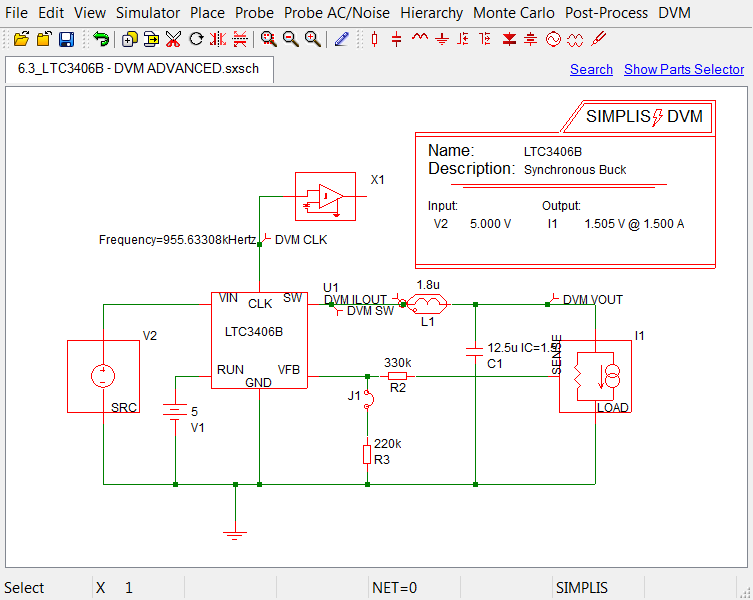
To change the schematic using jumpers, follow these steps:
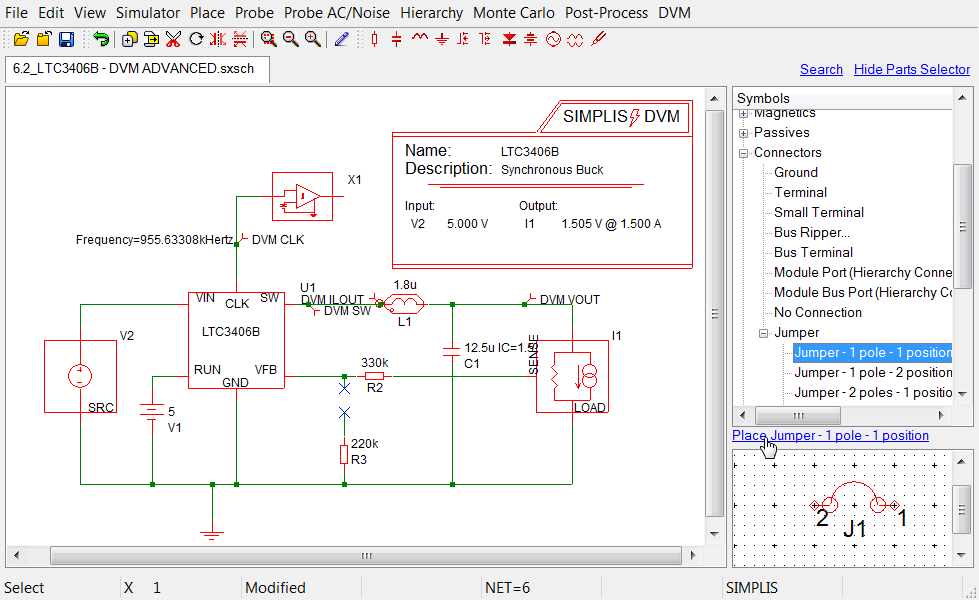
Draw a line to connect the jumper to the line between R2 and the LTC3406B.
Result: The correctly configured schematic shown below is available from SIMPLIS_dvm_tutorial_examples.zip at this path: LTC3406B/6.3_LTC3406B - DVM ADVANCED.sxsch
To control the jumpers from the testplan, follow these steps to edit the testplan available from SIMPLIS_dvm_tutorial_examples.zip at this path: testplans/6.1_var_start.testplan.
| Rows | Column |
Text to replace | Text to add |
6-8 |
jumper |
Close(J1) | |
6-8 |
label |
Default values | VOUT=1.505V |
12-14 |
jumper |
Open(J1) | |
12-14 |
label |
Default values | VOUT=600mV |
Result: Your schematic should now look like the following with the above modifications highlighted in red. A version of this testplan is available from SIMPLIS_dvm_tutorial_examples.zip at this path: testplans/6.3_jumpers.testplan.
| *** | ||||||
|---|---|---|---|---|---|---|
| *** 6.3_jumpers.testplan: Jumper testplan for DVM tutorial section 6.3 | ||||||
| *** | ||||||
| *?@ Analysis | Objective | Jumper | Source | Load | Label | |
| *** | ||||||
| Ac | BodePlot(OUTPUT:1) | Close(J1) | Source(INPUT:1, Nominal) | Load(OUTPUT:1, Light) | VOUT=1.505V|Bode Plot|Vin Nominal|Light Load | |
| Ac | BodePlot(OUTPUT:1) | Close(J1) | Source(INPUT:1, Nominal) | Load(OUTPUT:1, 50%) | VOUT=1.505V|Bode Plot|Vin Nominal|50% Load | |
| Ac | BodePlot(OUTPUT:1) | Close(J1) | Source(INPUT:1, Nominal) | Load(OUTPUT:1, 100%) | VOUT=1.505V|Bode Plot|Vin Nominal|100% Load | |
| *** | ||||||
| *** the jumper position sets the output voltage to 0.6V | ||||||
| *** | ||||||
| Ac | BodePlot(OUTPUT:1) | Open(J1) | Source(INPUT:1, Maximum) | Load(OUTPUT:1, Light) | VOUT=0.6V|Bode Plot|Vin Maximum|Light Load | |
| Ac | BodePlot(OUTPUT:1) | Open(J1) | Source(INPUT:1, Maximum) | Load(OUTPUT:1, 50%) | VOUT=0.6V|Bode Plot|Vin Maximum|50% Load | |
| Ac | BodePlot(OUTPUT:1) | Open(J1) | Source(INPUT:1, Maximum) | Load(OUTPUT:1, 100%) | VOUT=0.6V|Bode Plot|Vin Maximum|100% Load | |
After executing a single test from each group of tests, the overview report shows the test in the first set as "passed" with the default output voltage of 1.505V. The test in the second set with an output voltage of 600mV fails since the output voltage specifications were not changed in the control symbol when you used the jumper to change the output voltage setpoint.
Note: Any number of jumpers can be used for a schematic configuration. You can use multiple jumper-headed columns although, in theory, a maximum of three columns would be needed - one for each of the three possible jumper positions: open, pos1 or close, pos2.
You can include as many jumper reference designators as necessary using a comma between each designator in the list. For more information, see Jumpers in the DVM documentation.
© 2015 simplistechnologies.com | All Rights Reserved