3.3 Set up an AC Analysis
You are now ready to set up the AC analysis. Although you could run
an AC analysis on the schematic as it is, that analysis would have no
additional information because the schematic has no modulator.
For this exercise, you can use the last schematic you saved or open 3_SIMPLIS_tutorial_buck_converter.sxsch.
If the grid is not showing, go to the menu bar in the schematic editor,
and select View ▶ Toggle Grid.
In this Topic ShowHide
3.3.1 Prepare the Schematic
To prepare the previous schematic for the additions, follow these steps
in the Schematic Editor:
- To select components to move to the right, place the cross hair
at the top of the window between the V2
and R2 components and draw
a box around all of the components to the right as shown below:

Result: The selected components change
from red to blue.
- Place the cross hair on any blue line, and drag the selected components
20 grid points to the right.
- To delete each of the four wires highlighted in blue below, place
the cross hair on the wire, click the left mouse button, and then
Ctrl+X or press Delete.

- Click the V2 symbol and
drag it over two grid points and down so it is even with V1
as shown below:

▲ back to top
3.3.2 Add the New Components
To add the new components, follow these steps:
- From the Commonly Used Parts
category, double click Power Supply,
move the cross hair to the right of the V2 wave generator, and click
the left mouse button to place it.

- Repeat step 1, but place the cross hair above and to the left of
the D1 symbol.

- In the Commonly Used Parts
category, double click AC source
(for AC analysis), and place the cross hair above the V3 symbol and click to place the
new symbol.

- From the Parts Selector,
click the + in front of Analog Functions, and then double
click Comparator with Ground;
place the cross hair just to the right of V5
so that the lower connection lines up with the R2
symbol.

- At this point, click the line just above the U1
symbol text and drag the mouse to move it up 4 grid points.
- With the cross hair, draw a box around all of the symbols on the
left side (V1, V2,
V3, V5,
and U1), and drag them all
to the left 4 grid points.

- To place the SIMPLIS custom gate driver, follow these steps:
- In the Parts Selector, click the +
in front of MOSFET Drivers.
- Double click Totem-Pole Output
Driver.
- Place the cross hair between the comparator U1
and symbol R2, and
click to place the new symbol.

- To add the Bode Plot Probe from the Commonly Used Parts category,
double click Probe- Bode Plot - Gain/Phase
- w/ Measurement, and move the cross hair to the top of the
schematic between IL and L1; and then click to place it on
the grid.

Result: A
dialog appears for you to add measurements to this Bode Plot probe.
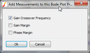
- Uncheck Gain Margin and Phase Margin, leaving only Gain
Crossover Frequency checked, and then click Ok.
▲ back to top
3.3.3 Saving your Schematic
To save your schematic, follow these steps:
- Select File ▶ Save As.
- Navigate to your working directory where you are saving your schematics.
- Name the file 4_my_buck_converter.sxsch.
▲ back to top
3.3.4 Add Wiring to the Schematic
Use the following diagram to add the wiring to your schematic:

From the menu bar, select File ▶ Save.
▲ back to top
3.3.5 Change Parameter Values
With the additional components, you have repurposed the waveform generator
V2 from the pulse source to the
modulator ramp voltage source. In the procedure below, you will set the
modulator ramp to 1V peak-peak so that the DC source (V3)
has a DC value (0.11V) equal to the duty cycle (11%) of the converter.
To change the parameter values for this analysis, follow these steps:
- Double click the V2 symbol.
Result: The Edit Waveform dialog box appears.
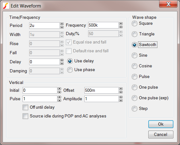
- On the right side of the dialog in the Wave Shape section,
select the Sawtooth
radio button.
- Set the Pulse value to
1V.
- Click Ok.
- Double click the V3 symbol
and change its DC Voltage
to 110mV; and then click Ok.
▲ back to top
3.3.6 Run the AC Analysis simulation
To run the AC analysis simulation, follow these steps:
- From the menu bar in the Schematic editor, select File
▶ Choose Analysis....
- On the right side of the dialog box, click to check AC.
Note: The POP check box is also selected and
grayed out so that both POP and AC analyses are performed.
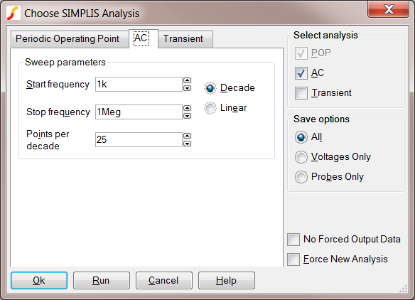
- Click Run
or click Ok
and then press F9.
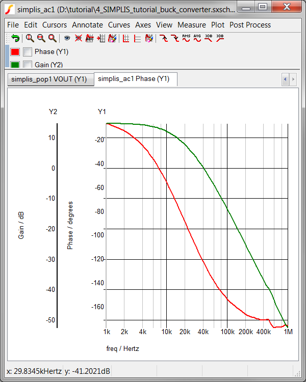
Result: The graph data output from this
run is shown below. As connected, the Bode plot probe generates the
control-to-output response of the converter.
- From the menu bar, select
File ▶ Save.
A schematic saved at this state can be downloaded here: 4_SIMPLIS_tutorial_buck_converter.sxsch.
In the next section, you customize
the graph output so that this graph is easier to read.
▲ back to top
© 2015 simplistechnologies.com | All Rights
Reserved