SIMPLIS Tutorial
SIMPLIS Tutorial
|
The Commonly Used Parts category in the Parts Selector contains all of the symbols for this schematic except the diode and the MOSFET. For these two, you will learn two other ways to place symbols: by navigating the Parts Selector and by using a keyboard shortcut.
In this Topic Hide
Step 1: To place the inductor,
diode, and MOSFET, follow these steps using the illustration below as
a general guide for placing the symbols.


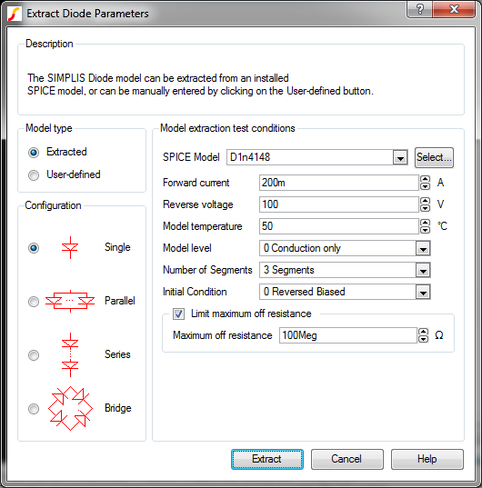
Result: The Extract Diode Parameters dialog
opens.
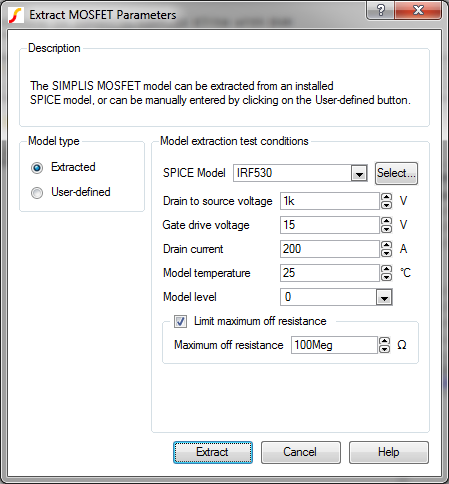
Note: The letter m is a keyboard shortcut for the Semiconductor -> NMOS 3 terminal discrete.
Result: The Extract MOSFET Parameter dialog
opens.
Step 2: To place the remaining symbols, follow these steps:

Legend |
Label |
Commonly Used Parts |
Shortcut |
Comments |
1 |
C1 |
Electrolytic capacitor |
|
No keyboard shortcut |
2 |
R1 |
Resistor (Z Shaped) |
4 |
|
3 |
V1 |
Power Supply |
v |
|
4 |
V2 |
Waveform Generator (Pulse, Ramp...) | w |
. |
5 |
R2 |
Resistor (Z Shaped) |
4 |
To rotate 270 degrees, press F5 three times. |
6 |
Ground |
g |
||
7 |
Probe1-NODE |
Probe-Voltage |
b |
|
8 |
Probe2-NODE |
Probe-Voltage |
b |
|
9 |
IPROBE1 |
Probe-Inline Current |
No keyboard shortcut |
Note: If you accidentally place an extra symbol, you can immediately remove it by typing Ctrl+Z.or by selecting Edit ▶ Undo from the menu bar. If you did not remove the extra symbol immediately after placing it, see 2.1.4__Remove_extra_symbols_and_wires.
To wire your symbols together, follow these steps:
Place the mouse pointer over
a symbol pin.
Result: The pointer changes to a pencil,
indicating that the schematic is in wiring mode.
To start a wiring segment, click the left mouse button.
To create corner points, click the left mouse button again until you reach the symbol to which you are drawing a connection.
When you finish drawing a segment, click the right mouse or press the Esc key.
Continue adding wires to
the schematic as shown below:

Note: If you accidentally place an extra wire, you can immediately remove it by typing Ctrl+Z.or by selecting Edit ▶ Undo from the menu bar. If you did not remove the extra wire immediately after placing it, see 2.1.4__Remove_extra_symbols_and_wires.
To remove an individual symbol or wire, follow these steps:
To remove a group of extra symbols and wires, follow these steps:
Note: To select extra wires and symbols. click anywhere on the schematic.
In some cases, you may want to remove wires that are inside the symbol
bounds of a comparator with the input pins shorted together as shown below.

To remove only the wire segments, follow these steps:


To save your schematic, follow these steps:
A schematic saved at this state can be downloaded here: 1_SIMPLIS_tutorial_buck_converter.sxsch.
© 2015 simplistechnologies.com | All Rights Reserved