2.2 Edit Component Values
Starting with the schematic that you saved in the previous section,
the next step is to change the component values to more accurately reflect
a practical design.
In this Topic ShowHide
2.2.1 Change Component Values
To change the output load resistor, follow these steps:
- Double click the R1 symbol,
making sure that you have the cross hair on the symbol - not on the
label.
Result: The Choose Component Value dialog
box appears.
- Change the Result to 120m as
shown below.

- Click OK.
- Repeat steps 1 through 3, changing the values as listed below:
| Reference Designator |
Component Name |
New Value |
| L1 |
Output Inductor |
680nH |
| R2 |
Gate Resistor |
1.5Ω |
| V1 |
Input Source |
12V |
▲ back to top
2.2.2 Change Capacitance Value
To change the output capacitor value, follow these steps:
- Double click the C1 symbol.
Result: The Edit Device Parameters dialog
appears.
- Change the Capacitance
value to 220uF as shown below.

▲ back to top
2.2.3 Change Curve Labels on Probes
Although not strictly necessary, the probes should be renamed to indicate
which circuit variables are represented on the graph waveforms.
To rename the probes, follow these steps:
- Double click the Probe1-NODE
symbol.
Result: The Edit Probe dialog opens.
- In the Curve label text
box, change the name to VOUT
 .
.
- Click OK.
- Repeat steps 1 through 3, changing the curve labels for the other
probes as indicated below:
| Old Curve Label |
Circuit Variable |
New Label |
| Probe2 NODE |
Switching Node |
SW |
| IPROBE1 |
Inductor Current Probe |
IL |
▲ back to top
2.2.4 Change MOSFET and Diode Models
The MOSFET and Diode require ratings that are appropriate to the specifications
of the design. The IRF530 MOSFET is a 100V device; therefore, you need
a 30V-rated device with an appropriate on-resistance. The Si4410DY is
a good option for this circuit.
To change Q1 from the IRF530 to the Si4410DY,
follow these steps:
- Double click the MOSFET
symbol.
Result: The Extract MOSFET Parameters dialog
appears.
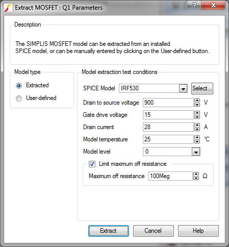
- Click the Select button
to the right of the SPICE Model field.
- In the Search field, type Si4410DY.
Result: Si4410DY is the only selection
in the Installed SPICE models list.
- Highlight Si4410DY, and
then click OK.
- Click Extract.
Result: The SPICE model for Q1
changes to Si4410DY.
To change the Diode to use the built-in IDEAL device, follow these steps:
- Double click the D1 symbol.
Result: The Extract Diode : D1 Parameters
dialog.
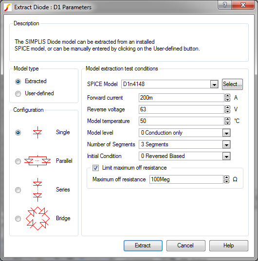
- Click the Select button
to the right of the SPICE Model field.
- In the Search field, type ID.
Result: IDEAL is the only selection in
the Installed SPICE models list.
- Highlight IDEAL, and then
click OK.
- Click Extract.
Result: The
Diode symbol now appears with the IDEAL label.
▲ back to top
2.2.5 Configure the Waveform Generator
The waveform generator is a flexible device that can represent a number
of periodic waveform types. To drive the MOSFET Q1,
you need a pulse generator with a specified pulse width, frequency, and
amplitude.
To set up the Waveform Generator as a Pulse source, follow these
steps:
- Double click the waveform generator symbol.
Result: The Edit Waveform dialog appears.
- On the right side of the dialog in the Wave Shape section,
select the Pulse radio
button.
- In the middle column at the top, change Frequency
to 500k and Duty
Cycle to 11.
- In the first column near the bottom of the dialog, change Pulse to 5.
Note: As you make each change, the corresponding
values are recalculated but the recalculated values do not appear
until you click in another text field to make the next change.

- Click Ok to save the new
parameter values.
The design is now at a point where you can start your first simulations
and then begin further optimization.
▲ back to top
2.2.6 Saving your Schematic
To save your schematic, follow these steps:
- Select File ▶ Save As.
- Navigate to your working directory where you are saving your schematics.
- Name the file 2_my_buck_converter.sxsch.
A schematic saved at this state can be downloaded here:
2_SIMPLIS_tutorial_buck_converter.sxsch.
▲ back to top
© 2015 simplistechnologies.com | All Rights
Reserved