Advanced SIMPLIS Training
Advanced SIMPLIS Training
|
In this Topic Hide
Some common and uncommon features of the SIMetrix/SIMPLIS User Interface, including:
Using the new command shell file menu File Training Module 1, open the 1.1_SelfOscillatingConverter_POP_AC_Tran.sxsch schematic.
Press F11 to open the command (F11) window.
Result: A text editing window opens on
the bottom of the schematic. There is a horizontal slider bar to change
the size of the text window.
Every schematic and schematic component file has a command, or F11 window. During the netlist process, the contents of the F11 window are placed in the netlist before any content from that schematic level is added. The F11 window is a very handy place to put additional content, including subcircuit models, graphing statements, and variable statements, etc.
The F11 window of the current schematic is shown below:
.SIMULATOR SIMPLIS
.AC DEC 20 10 100k
.PRINT
+ ALL
.OPTIONS
+ PSP_NPT=8001
+ POP_OUTPUT_CYCLES=3
+ NEW_ANALYSIS
.POP
+ TRIG_GATE={TRIG_GATE}
+ TRIG_COND=0_TO_1
+ MAX_PERIOD=1m
+ CONVERGENCE=10f
+ CYCLES_BEFORE_LAUNCH=3
.TRAN 500u 0
.var RLoad=2.5
*** graphs flux linkage vs. I on pop or transient.
.PRINT V(#FLUX)
.GRAPH "XY( :#FLUX , :L4#P )" axisType="auto" persistence=1
graphName="BH" curveLabel="PWL Inductor"
+ analysis="pop|tran" xLog="auto" yLog="lin"
nowarn=true xLabel="Magnetizing Current" yLabel="Flux
Linkage" xUnit="A" yUnit="Weber"
.SIMULATOR DEFAULT
.var C6_val=100n
.var C5_val=22n
The first section of the F11 window contains the analysis directives. When you execute the schematic menu Simulator Choose Analysis..., the results from the dialog are saved to the top of the F11 window. Because the dialog will manipulate the F11 window content, users should place any additional content below the last analysis statement. The first user entry is the line:
.var RLoad=2.5
This is a variable statement, the load resistor with reference designator uses this variable in an expression: {RLoad}. Whenever a variable or set of variables and constants is placed inside the curly brackets {}, this tells the simulator to evaluate the expression contained between them. In this case, the simulator will replace the {RLoad} expression with the numeric constant 2.5 prior to the simulation.
The next portion of the F11 window is a custom graph command. There are two lines which constitute a custom graph statement:
.PRINT V(#FLUX)
.GRAPH
"XY( :#FLUX , :L4#P )" axisType="auto" persistence=1
graphName="BH" curveLabel="PWL Inductor"
+ analysis="pop|tran" xLog="auto" yLog="lin"
nowarn=true xLabel="Magnetizing Current" yLabel="Flux
Linkage" xUnit="A" yUnit="Weber"
The first line tells the simulator to output the voltage vector named #FLUX on the schematic. You will learn more about finding the node names on a schematic later in this section.
The second line is a call to the actual graphing function. The .GRAPH entry is the underlying mechanism used by the fixed probes. This graph statement generates a x-y plot of the FLUX voltage versus the positive pin current of the PWL inductor L4. The details of the .GRAPH statement are covered in topic 2.1.5 The .GRAPH Statement. You can also refer .GRAPH statement syntax in the Simulator Reference Manual.
The final three lines in the F11 window are a .SIMULATOR control and two more variables. Both the .SIMULATOR control and variables will be covered in detail in The .SIMULATOR_Control topic.
| CAUTION: When you copy a schematic using the File Save As... menu or by copying and pasting in a Windows Explorer window, the F11 window contents are also copied. Keep this in mind, as the original schematic may have F11 content which is not needed, or worse, detrimental to the new design. |
Hover your mouse over any wire on the schematic and the node name is displayed on the bottom bar of the schematic window.
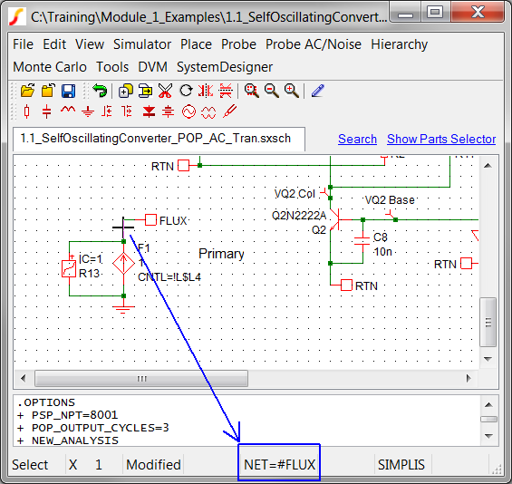
While you are here, there is a wealth of information on the bottom bar of the schematic. From left to right:
There are two types of schematic files used in SIMetrix/SIMPLIS.
A Schematic file has no symbol and is the "top level", or parent, schematic. This schematic has all the analysis information contained in the F11 window. Some users might think of this type of schematic as a "test bench." Schematic files have the extension .sxsch or .wxsch.
A Schematic Component file includes both a symbol and a schematic containing hierarchical ports which match the pins on the symbol. The Schematic Component file is a self contain module containing both the electrical model information in schematic form, and the symbol which is required to connect the model to a parent schematic. Schematic Component files have the extension .sxcmp.
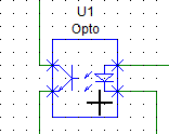
The 1.1_SelfOscillatingConverter_POP_AC_Tran.sxsch schematic contains one model implemented with a Schematic Component file, the opto-coupler U1. To view the schematic for the opto-coupler,
Select
U1.
Result: The symbol turns from red to blue,
indicating that it is selected.
Press
the keyboard shortcut key combination Ctrl+E,
or use the schematic menu Hierarchy
Descend Into.
Result: The schematic view of the Gen_Opto
Schematic Component opens.
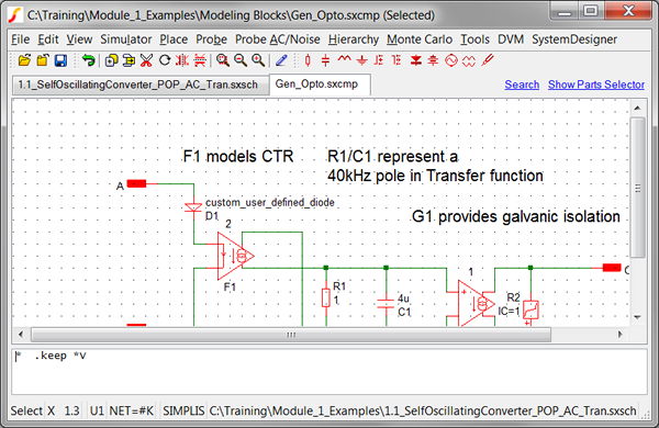
Press
the Home key.
Result: the schematic zooms to fit all
symbols and wires on the Gen_Opto.sxcmp schematic.
To ascend a level to
the parent of U1, Press Ctrl+U,
or use the schematic menu Hierarchy
Ascend.
Result: The parent schematic tab 1.1_SelfOscillatingConverter_POP_AC_Tran.sxsch
comes into focus.
Lets pause here and discuss the new information on the bottom bar of the Schematic Component. Two items have changed from the Schematic window:
U1 NET=#K : The net name nearest the cursor is now preceded with the reference designator of the schematic component. If there were multiple levels, the reference designators would be separated by a ".", such as U1.U4.
The full path to the parent schematic is shown in the lower right hand corner.
There are several ways to edit the symbol view of a Schematic Component file. Here are the two most common methods.
From the parent schematic, select U1.
Right
click to bring up the context menu and select Edit Symbol:
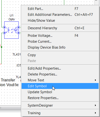
Note: The training material shortcut Shift+S will execute the same menu item.
OR
From
the Gen_Opto.sxcmp schematic view, select Hierarchy
Open/Create Symbol for Schematic...
Note: The training material shortcut S will execute the same menu item.
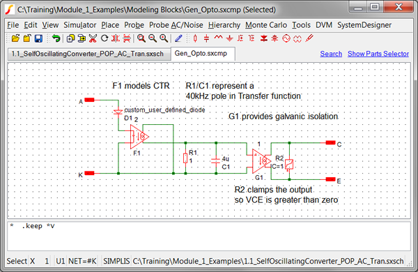
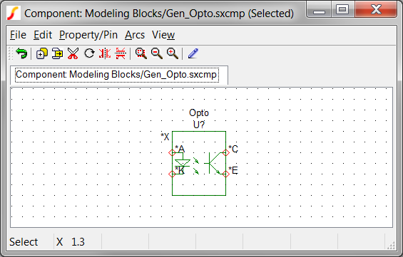
Both these methods will open
the symbol editor to the symbol contained in the Gen_Opto.sxcmp file:
SIMetrix/SIMPLIS uses four windows:
A few handy shortcuts will help navigate between the windows:
Ctrl+T : Tabs between schematic, symbol, and graph Windows.
Space Bar : Brings the Command Shell into Focus.
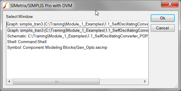
Ctrl+W
: Brings up a selection dialog to select which window to focus on:
The program automatically remembers the size and position of each pop-up dialog every time you close the dialog. The four main windows are handled differently - you have to direct the program when you want to save the position of the windows. To setup the windows on your desktop,
Manually adjust the four windows to have the size and screen position you desire.
If you don't have a graph viewer open, press F10 to open a blank graph viewer.
To open the symbol editor, use the Command shell menu File Symbol Editor New Symbol.
Once your windows are sized and positioned, select the command
shell menu: File
Windows Save Desktop.
Result: Your desktop preferences are saved.
No message is produced.
Try moving and resizing a window. To restore the saved desktop, select the menu File Windows Restore Desktop.
SIMetrix/SIMPLIS will use your saved settings every time the program starts.
Every schematic and schematic component file has a F11 window.
The contents of the F11 window are included in the simulation prior to any netlist generated from the schematic.
Analysis directives are stored in the F11 window.
Schematic Component files contain both the Symbol and Schematic view of a model.
The parent-child hierarchy model presented here will be exploited in future chapters. This concept offers a very powerful way to isolate functional blocks.
Please fill out the Module # 1 Evaluation form at surveymonkey.com.
© 2015 simplistechnologies.com | All Rights Reserved