Advanced SIMPLIS Training
Advanced SIMPLIS Training
|
To download the examples for Module 5, click Module_5_Examples.zip
In this Topic Hide
Adding parameters to primitive models, such as resistors, capacitors,
and inductors, is easy. You simply enclose the parameter value in curly
braces when you enter it in the parameter-editing dialog. For example,
the resistor pictured below uses the parameter RLoad
for the resistance value:

The text {RLoad} is an expression.
In this case, the expression is just the parameter itself; however, you
can define the expression as any arbitrary mathematical expression involving
parameters and functions as shown in the examples below:
| Expression | Description |
| {Vin} | Simple expression involving a single parameter |
| {Vout_nom/Iload} | An expression using two parameters, in this case, to calculate a load resistor |
| {C5_val*Gauss(0.05)} | An expression using a single parameter and a probability distribution function |
Parameters are often defined in the command (F11) window of the schematic using a .VAR statement. In the next exercise, you will learn how parameter values are used in a primitive capacitor model.
Open the schematic 5.1_SelfOscillatingConverter_POP.sxsch.
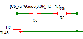
In the TL431 compensation network on the schematic, find
the capacitor C5 and notice
its parameterized value, which is the same as the last expression
in the Example Expressions table above.
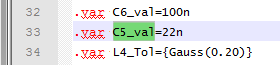
Press F11 to open the command (F11) window, and then scroll down to the line which defines the parameter C5_val:
Press F9
to run the simulation.
Result: The simulation executes and the
POP waveforms for the converter are displayed on the graph viewer.
From the SIMetrix/SIMPLIS command shell menu, select SIMPLIS
Edit Netlist (before preprocess).
Result: The netlist opens in Notepad++.
To find the text C5_val in the netlist, follow these steps:
Type the shortcut Ctrl+F to open the search dialog.
Type C5_val in the search box.
In the Direction group, select the Down radio button.
Click the Find
Next button.
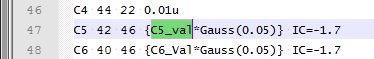
Result: The netlist scrolls to line
#33 where a .VAR statement defines the parameter. This is the
same statement as in the F11 window of the schematic.
Click the Find Next
button again.
Result: The netlist scrolls to line
#47 where the parameter C5_val is used to set the value of the primitive capacitor
C5.
Parameters defined in the command (F11) window can be used to parameterize primitive models.
The capacitor C5 is a primitive capacitor, which is a built-in SIMPLIS model.
In the 3.0.1 What Happens When You Press F9? topic, you learned how the netlisting process works. In that topic you learned how the netlister substitutes symbol properties in the SIMPLIS_TEMPLATE or TEMPLATE property to generate the netlist entry for a symbol.
The resulting netlist instantiation line defines the electrical device used in the simulation. The instantiation line for the capacitor C5 is as follows:
The capacitor value is stored on the VALUE
symbol property which includes both the parameter expression and the initial
condition:
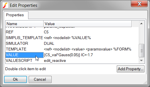
The point here is that although the parameter value is defined in the F11 window, the expression containing the parameter must be stored on the VALUE symbol property so that the netlist entry can be generated. As the netlister processes each symbol, it does not know the parameter value is defined in the F11 window. Instead, the netlister simply substitutes the VALUE symbol property into the SIMPLIS_TEMPLATE in place of the text %VALUE%.
The capacitor in this example stores multiple electrical parameters on a single symbol property. This is the single property method and is covered in the Single-Property_Method topic. One of the other ways to store parameters is the Multi-Property_Method, which stores each electrical parameter on a single symbol property.
By default, parameters are local to the schematic where the parameter is defined. Separate files for each schematic create multiple hierarchy levels. At any schematic level, all parameters defined in the command (F11) window of the schematic can be used on symbols located on that schematic. Parameters defined in one schematic cannot be used in other schematics unless the parameter is passed down through the symbol or unless the parameter is global. This allows the same parameter name to be used in different schematic components with different values.
The next exercise explores the scope of parameters.
In the opened schematic, 5.1_SelfOscillatingConverter_POP.sxsch, select the optocoupler U1.
Type Ctrl+E to descend into the schematic of the optocoupler U1.
Press F11 to open the
command (F11) window for the schematic.
Result: The command (F11) window opens
and displays a single .VAR statement:
To comment out the .VAR statement, type a single asterisk (*)
in front of the .VAR
CTR=2 statement.
Result: The command (F11) window content
is now as follows:
Select the top level schematic tab: 5.1_SelfOscillatingConverter_POP.sxsch.
In the command (F11) window, locate the same .VAR statement which is the second to last statement in the F11 window.
To uncomment the .VAR statement, delete the asterisk (*).
Result: The command (F11) window of the
top level schematic now has the .VAR statement:
Press F9 to run the
simulation.
Result: The simulation halts because the
value for the proportionality constant (gain) of the current controlled
current source F1 cannot be found at the optocoupler hierarchy level.
An error similar to the following appears in the command shell:
****************************************
<<<<<<<< Error Message ID: 1038 >>>>>>>>
input file C:\Training\Module_5_Examples\SIMPLIS_Data/5.1_SelfOscillatingConverter_POP.deck, line 172:
F1 9 6 VF1$TP_CCCS {CTR}
A number to represent the value
for `proportionality constant' is expected at the
location where `{CTR}' occupies.
In this exercise, you attempted to use the parameter CTR in a hierarchical level other than the top level where CTR is defined. Since the parameters defined at each hierarchy level are independent of each other, the CTR parameter is undefined at the optocoupler level and an error is generated. In the next exercise, you will use the .GLOBALVAR statement to make CTR a global parameter.
In the command (F11) window of the top level schematic, comment
out the .VAR
CTR=2 and uncomment the .GLOBALVAR
CTR=2 line.
Result: The command (F11) window appears
as follows:
*.VAR CTR=2
.GLOBALVAR CTR=2
Press F9 to run the
simulation.
Result: The simulation now runs successfully
as expected.
When you define a parameter using the .GLOBALVAR statement, that parameter is available at that hierarchy level and at all lower levels in the hierarchy. This means that the parameter CTR is available at both the top level schematic and at the optocoupler hierarchy level. While this works, there are real and significant dangers of using .GLOBALVAR to parameterize the model.
Every optocoupler schematic component in the design will have the same CTR parameter. There is no way to change this parameter when a .GLOBALVAR statement is used to define its value.
If the optocoupler is placed on a new schematic, the CTR parameter might already be defined. This "namespace collision" is exactly what you want to avoid when parameterizing models.
Someone unfamiliar with the design will not understand where the parameter CTR is defined since CTR is not defined anywhere on the Gen_Opto.sxcmp schematic.
The Gen_Opto.sxcmp schematic component is not a stand-alone entity - it requires a globally defined parameter. This hinders modularity and portability.
In topic 5.1 Passing Parameters Into Subcircuits Using The SIMPLIS_TEMPLATE Property, you will learn the recommended way to pass parameters into subcircuits.
Primitive models can be parameterized at the schematic level where they are used by entering the .VAR statement in the command (F11) window and by adding the expression to the symbol value.
By default, parameters are local to the hierarchy level.
Although global parameters can be defined, the recommended method is to pass local parameters down through the hierarchy as explained in 5.1 Passing Parameters Into Subcircuits Using The SIMPLIS_TEMPLATE Property.
5.1 Passing Parameters into Subcircuits Using the SIMPLIS_TEMPLATE Property ▶ |
© 2015 simplistechnologies.com | All Rights Reserved