DVM - Design Verification Module
DVM - Design Verification Module
|
The Basic DVM control symbol holds the minimum amount of information that is required to run DVM. The Full Power Assist Control Symbol stores additional information, such as specifications for the sources and loads, as well as performance specifications. The DVM control symbol dialog consists of two areas:
In this Topic Hide
To add a Basic DVM control symbol to a working schematic, follow these steps:
Double click the symbol.
Result: The SIMPLIS DVM Control Panel dialog
opens for you to enter the information that is described in the following
sections.
The Circuit Specifications page allows you to define circuit descriptions and specifications that DVM uses when measuring and checking scalar values in the simulation. On this dialog, you also specify the number of DC inputs, AC inputs, and outputs. Additional pages appear for each input and for each output as shown in the page selection panel below.
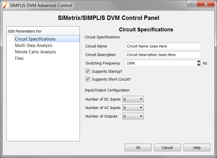
| Label | Parameter Description |
| Circuit Name | Name of the circuit as it will appear in the DVM report; for display purposes only. |
| Circuit Description | Description of the circuit under test which appears in the DVM Control symbol; for display purposes only. |
| Switching Frequency | Nominal switching frequency used to calculate simulation timing for DC/DC test objectives |
| Supports Startup? | If checked, the startup tests will be performed; if not checked, the startup tests will be skipped. |
| Supports Short Circuit? | If checked, the short circuit tests will be performed; if not checked, the short circuit tests will be skipped. |
| Number of DC Inputs | On a Basic DVM Control Symbol, the number of DC
and AC inputs and the number of outputs will all be zero.
Increasing both the number of inputs and the number of outputs
to one or more will convert the Basic control symbol into a Full Power Assist DVM
Control Symbol.
The numbers that you select in these three fields dynamically change the page selection list to accommodate the number of AC and DC inputs and the outputs that will then be available for you to configure. |
| Number of AC Inputs | |
| Number of Outputs |
The SIMPLIS Multi-Step analysis allows you to step a design parameter over a range of values using a decade-step or linear-step interval. You may also step values over a defined list of parameter values. One advantage of using a multi-step analysis over multiple DVM tests is the multi-core capability which is part of the Pro and Elite license packages. The multi-core capability runs steps in parallel on multiple processor cores and will greatly reduce the simulation time required for the multi-step analysis.
For more information, see the Multi-Step Analysis topic.
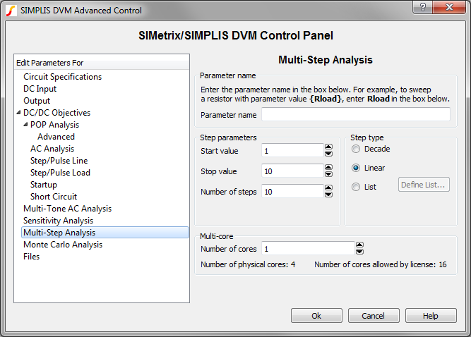
| Parameter name | |
| Parameter name | The name of the stepped parameter. The schematic symbols should
be parameterized with this parameter name in braced {} substitutions
as at the top of the dialog above.
Note: You can automatically change symbol property values by using the Change testplan entry. |
| Step Parameters and Step type | |
| Start value | The starting value for the parameter step, used with decade and linear steps |
| Stop value | The ending value for the parameter step, used with decade and linear steps |
| Number of steps | The number of steps for the decade or linear steps |
| Step type | The step type can be one of the following:
|
| Multi-core | |
| Number of cores | The number of cores used for the simulation. The Pro and Elite licenses allow the use of 4 and 16 cores respectively. |
The Monte Carlo analysis allows you to investigate the effect of random parameter value changes on your circuit. The Monte Carlo analysis assumes that you have set up your circuit with statistical parameter distribution functions.
For more information, see the Monte Carlo Analysis topic.
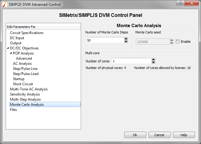
| Parameters | |
| Number of Monte Carlo Steps | The number of steps, or simulations, to run |
| Monte Carlo Seed | The seed value for the Monte Carlo simulation. The seed value starts the pseudo-random number generator at a specific value. Subsequent seeds follow a predictable pattern, which makes the Monte Carlo simulation repeatable. |
| Multi-core | |
| Number of cores | The number of cores used for the simulation. The Pro and Elite licenses allow the use of 4 and 16 cores respectively. |
The Files page allows you to do the following:
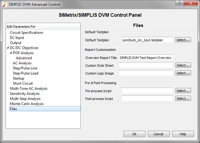
Default Testplan: used when you select either DVM ▶ Run Schematic's Default Testplan or DVM ▶ Run Entire Schematic's Default Testplan from the menu bar. |
|
| Default Testplan | Specifies the default testplan to be used with this schematic. |
Report Customization: Options to customize the appearance of the DVM report |
|
| Overview Report Title | The title used on the overview report. The titles for individual test reports can be changed with the HTMLTitle testplan entry. |
| Custom Style Sheet | Cascading Style Sheet (CSS file) to use with the DVM report |
| Custom Logo Image | Portable Network Graphics (PNG) file to use with the DVM report |
Pre & Post Processing |
|
| Pre-process Script | SIMetrix script to be executed immediately before launching each simulation; this allows you to change schematic values or analysis statements before running the test. Preprocess scripts are executed after all Objective entries are processed which allows users to override any schematic changes made by DVM. |
| Post-process Script | SIMetrix script to be executed immediately after each simulation successfully completes; this allows you to perform waveform manipulation and to create custom scalar and specification values. |
© 2015 simplistechnologies.com | All Rights Reserved