Data Handling and Keeps
Keeps form part of a system to limit the amount of data that is output during a simulation. For some designs the data output can be too great to fit in the available disk space. In the case of multi-core multi-step runs, it is possible for the rate at which data is generated to exceed the write speed of the disk system leading to slow run times. In these situations, the data output needs to be restricted.
By default, all voltage and currents shown in schematics are saved. This includes data from child schematics in hierarchical designs but excludes signals inside ASCII subcircuit models.
To restrict data output you can use the Data tab within the choose analysis dialog box:
- Select menu
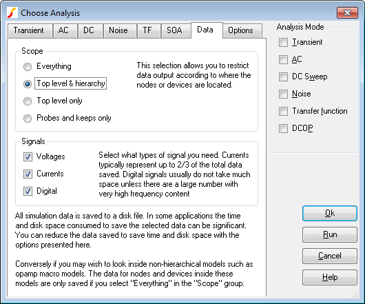
- Click on the Data tab. This will show the following:
In this topic:
Scope Options
In the following description, ASCII Subcircuits means subcircuits that are not created by the SIMetrix hierarchical schematic editor. The SIMetrix hierarchical schematic editor uses SPICE subcircuits (using .SUBCKT) as its base but decorates the subcircuit definitions with a special comment to distinguish them from subcircuits from other sources. ASCII subcircuits would typically include models for devices such as opamps along with foundry models for integrated circuit processes.
| Everything | All data will be saved including signals inside ASCII subcircuits. |
| Top level & hierarchy | Data from the root schematic and all hierarchical child schematics will be saved. Data for fixed probes and keeps (see below) will also be saved. Data inside ASCII subcircuits will not be saved. |
| Top level only | Only signals from the root schematic will be saved. Data for fixed probes and keeps (see below) will also be saved. |
| Probes and keeps only | Only signals attached to fixed probes or keeps (see below) will be saved. |
Signals Options
Signals are classed as voltages, currents or digital. Digital signals are those created by the event driven simulator and in some cases by the Verilog-HDL interface. Digital signals generally take up much less space as data is only stored when they change state whereas for analog signals data is stored on every time step.
In most applications disabling the saving of currents will reduce the amount of data saved by a very significant amount and this may be sufficient to resolve any problems caused by large amounts of data being saved. In this case current keeps may be used to save specific currents as required.
With some or all data output inhibited the options described above, you can add keep symbols to the schematic to select specific voltages or currents to be saved.
Keep symbols use the underlying simulator statement .KEEP. For information on the comprehensive features of .KEEP, please refer to the Simulator Reference Manual/Command Reference/.KEEP.
To Add a Voltage Keep to a Schematic
- From the Part Selector navigate to Probes and Connectors ???MATH???\rightarrow???MATH??? Keeps ???MATH???\rightarrow???MATH??? Voltage Keep.
- Place device on desired schematic net.
To Add a Current Keep to a Schematic
- From the Part Selector navigate to Probes and Connectors ???MATH???\rightarrow???MATH??? Keeps ???MATH???\rightarrow???MATH??? Current Keep.
- Place device directly on a device pin.
| ◄ Convergence | Simulator Options ▶ |