3.1 Editing the Schematic
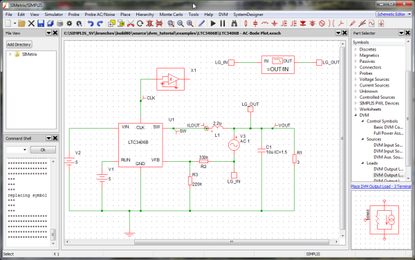
To open the schematic for this tutorial, follow these steps from the directory where you unzipped the file as explained in 2.0 Getting Started.
- Navigate to the following path: LTC3406B/Test_Ckts/
- To open the schematic, double click the LTC3406B-AC-Bode_Plot.sxsch file or drag that file into the SIMetrix/SIMPLIS Command Shell.
In this section, you will configure the schematic using a Full Power Assist DVM control symbol and prepare to run a built-in testplan.
In this topic:
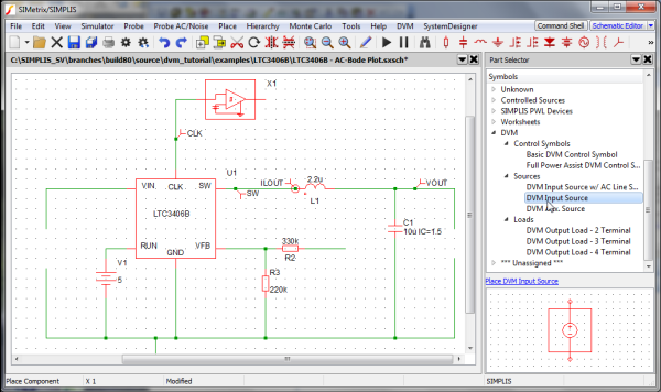
3.1.1 Adding an Input Source Symbol
To add the input source, follow these steps:
- Remove the DC voltage source V2 on the left side of the schematic.
- From the parts selector, choose , and place the symbol where you removed V2.
3.1.2 Adding a 3-Terminal Output Load Symbol
The 3- and 4-terminal DVM output loads have a SENSE (3-terminal) or a differential SENSE (4-terminal) connection. These extra pins allow DVM to include the injected AC perturbation source and Bode plot probe that are required for closed-loop AC analysis. DVM automatically inserts these components into the managed load subcircuit definition for the Bode plot tests. This tutorial illustrates use of the 3-terminal output load.
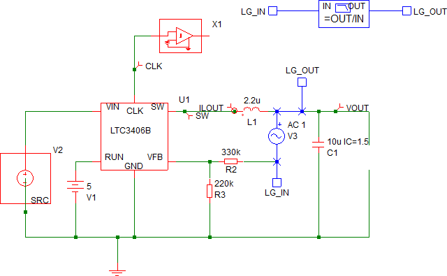
To add the 3-terminal output load, follow these steps:
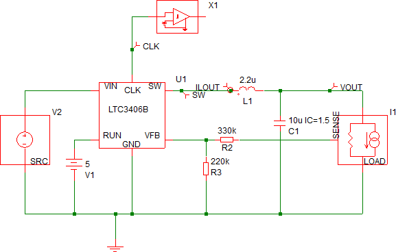
- Remove the R1 resistor from the right side of the schematic.
- Using the image below as a guide, remove the following symbols and wires shown in
blue:
- Bode Plot probe
- LG_IN and LG_OUT at the top of the schematic
- AC source V3
- LG_IN, LG_OUT
- The connections between these symbols near the center of the schematic.
- From the parts selector, choose , and place it where you removed R1.
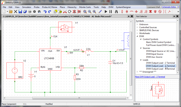
- Connect the SENSE terminal on the DVM 3-terminal output load to the feedback
resistor R2. Note: The SENSE terminal provides the output voltage feedback information to the converter control loop. During Bode plot tests, the small signal AC source is inserted between the positive load terminal and the SENSE terminal and perturbs the control loop. For all other test objectives, the SENSE terminal is shorted to the positive output terminal of the managed load. The schematic should appear as shown below:
3.1.3 Adding the Full Power Assist Control Symbol
To place a DVM control symbol for Full Power Assist, follow these steps:
- From the parts selector, choose .
- Place the symbol at the top of the schematic.
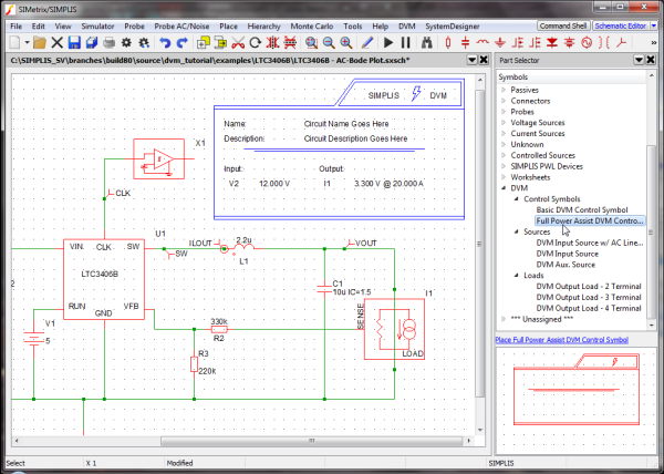
3.1.4 Verifying Source and Load Management
When the Full Power Assist control symbol is added to a schematic which has DVM sources and loads, the existing DVM sources and loads are automatically set up to be managed by DVM for each simulation test. Managed sources and loads have specification information stored on the control symbol. The specifications stored on the DVM control symbol are used by DVM to set the source voltage and load current during a DVM test.
To verify that your sources and loads are managed, follow these steps:
- Check the control symbol for the reference designators which, in this schematic, are
V2 and I1, as shown below.
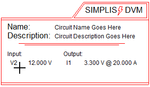
- If your control symbol contains the designators, go to section 3.1.6 Setting Control Parameters; otherwise, go to the next section, 3.1.5 Setting up Managed Sources and Loads, to configure the control symbol to have managed sources and loads.
3.1.5 Setting Up Managed DVM Sources and Loads
If the control symbol was added before either the source or load was placed, it looks like the image below, indicating that the DVM control symbol does not yet have managed sources and loads.
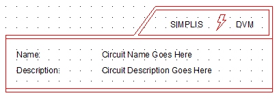
To manage the DVM sources and loads, follow these steps:
- Select the DVM control symbol so that the symbol changes from red to blue.
- Double click on the DVM control symbol on the schematic to open the DVM Control Panel.
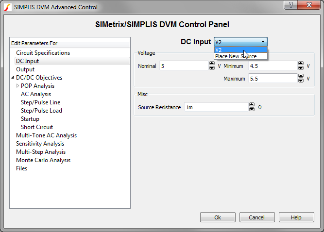
- Click on DC Input in the page-selection box on the left, and from the
drop-down menu at the top of the DC Input page, select V2.
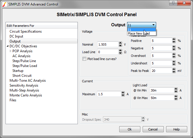
- Click on Output in the selection box, and from the menu at the top of the
Output page, select I1.
- Click Ok to save the managed load and source information.
3.1.6 Setting Control Parameters
The DVM control symbol has been configured with one managed input source (V2) and one managed output load (I1). When you placed the control symbol on the schematic with analysis directives already set from the Choose Analysis ... dialog, these directives are copied onto the control symbol. Since the program has no way of knowing what the input and output voltages and load currents are, you need to change these parameters to suit this particular circuit.
To change the control parameters, follow these steps:
- Double click on the DVM control symbol. Result: The SIMetrix/SIMPLIS DVM Control Panel opens.
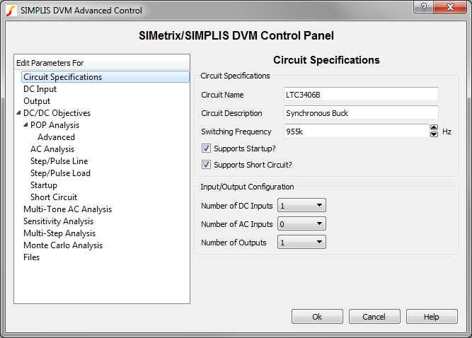
- On the Circuit Specifications page, set the values as listed in the following table.
Parameter Value Units Circuit Name LTC3406B Circuit Description Synchronous Buck Note: Leave the default values for the other fields on this page. - Click on DC Input in the page-selection box on the left side of the control
panel, and then enter the values listed below.
Parameter Value Units Voltage Nominal 5 V Minimum 4.5 V Maximum 5.5 V Misc. Source Resistance 1m (default) Ohm - Click on Output in the page-selection box, and enter the values listed
below.
Parameter Value Units Voltage Nominal 1.505 V Load Line 0 (default) Ohm Tolerances Pos. 5 (default) % Neg. 5 (default) % Overshoot 5 (default) % Current Maximum 1.5 A Light Load @ Vin Min 30m A @ Vin Max 50m A - Click the arrow in front of DC/DC Objectives in the page-selection box, and then click on POP.
- Verify that Use "Pop Trigger" schematic device is checked.
- Click Ok to save the specification changes.
- Save the schematic.Result: At this point, the schematic is properly configured for DVM Full Power Assist.
To view an updated schematic saved at this state, follow these steps from the directory where you unzipped the file as explained in 2.0 Getting Started.
- Navigate to the following path: LTC3406B
- To open the schematic, double click the LTC3406B-DVM_ADVANCED.sxsch file or drag that file into the SIMetrix/SIMPLIS Command Shell.