2.4 Edit Parameter-Extracted Models
This section of the tutorial explains how to edit parameter-extracted models. You will start with the schematic that you saved in 2.3 Edit Multi-Level Models and then continue to make changes that more accurately reflect a practical design.
In this topic:
Key Concepts
This topic addresses the following key concepts:
- The correct model extraction voltage, current, and temperature parameters are required to produce an accurate PWL MOSFET model.
- The MOSFET SPICE model is not used in SIMPLIS simulations, instead SIMPLIS uses a PWL model which accurately reflects the actual SPICE model behavior.
What You Will Learn
In this topic, you will learn the following:
- How to change the MOSFET SPICE model.
- How to extract a PWL model.
2.4.1 Change MOSFET SPICE Model
In section 2.1 Add Symbols and Wires, you placed parameter-extracted models for the MOSFET and diode without considering the suitability of the models. The IRF530 MOSFET is a 100V device with a high on-resistance; when what you need is a 30V-rated device with a lower on-resistance. This design will use the Si4410DY MOSFET, which has a drain-source rating of 30V and an on-resistance of approximately 18mΩ.
To change Q1 to use the Si4410DY model, follow these steps:
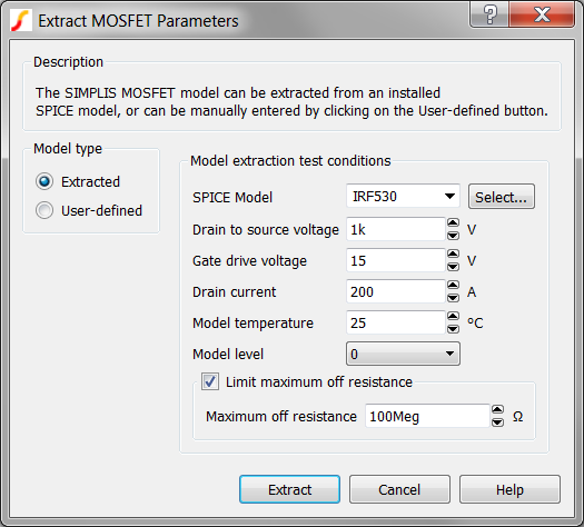
- Double click the MOSFET symbol. Result: The Extract MOSFET Parameters dialog opens.

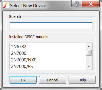
- Click the Select button to the right of the SPICE Model field.Result: The Select New Device dialog opens.

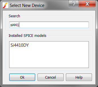
- In the Search field, type si441. Result: Si4410DY is the only model which matches the sub-string si441 in the Installed SPICE models list.

- Click on the Si4410DY, and then click Ok.Result: On the Extract MOSFET Parameters dialog, the SPICE model for Q1 changes to Si4410DY.
- Leave the dialog box open to continue after reading about the parameter extraction routine.
2.4.2 Change the Model Extraction Conditions
Next, you need to change the model extraction conditions to the values used in this circuit. The parameter extraction routine requires the following four circuit parameters:
- The Drain to source voltage in order to determine the MOSFET capacitance values.
- The Gate drive voltage to determine the conduction characteristics.
- The Drain current to determine the threshold and transconductance of the MOSFET.
- The Model temperature, which affects most parameters since this is the temperature at which the SPICE simulation is performed.
For the optimum model accuracy, all four parameters should accurately reflect the voltage, current, and temperature of the actual circuit.
To change the model extraction conditions, follow these steps:
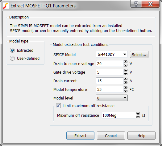
- With the Extract MOSFET dialog open from the previous instructions, enter the values as
shown in the image below.
Parameter label Value Drain to source voltage 20 Gate drive voltage 5 Drain current 15 Model temperature 55 Result: The dialog should now look like the following:
- Click Extract.Result: The SPICE model Si4410DY is simulated at the supplied test conditions and a PWL model is extracted for use in SIMPLIS.
2.4.3 Save your Schematic
To save your schematic, follow these steps:
- Select .
- Navigate to your working directory where you are saving your schematics.
- Save the file as 2_my_buck_converter.sxsch.
- When prompted to overwrite the existing file, click Yes.Note: You will use this schematic in the next section, 2.5 Change to a User-defined Model.