5.3 Passing Parameters Through Multiple Hierarchy Levels
To download the examples for Module 5, click Module_5_Examples.zip.
In this topic:
What You Will Learn
- How the SIMPLIS_TEMPLATE property allows you to explicitly pass parameters through the symbol-to-subcircuit interface
- How the .GLOBALVAR statement allows you to promote a local parameter to a global parameter
Getting Started
In the last topic, 5.2.2 Adding Tabbed Parameter-Editing Dialogs, you learned how to add a parameter-editing dialog to a schematic component. The resulting schematic component is parameterized and easy to use; however, parameters passed into that schematic component can be used only on that hierarchical level. To manage parameters passed into schematic components at lower levels, you have two options:
- Pass the parameters through the SIMPLIS_TEMPLATE
- Make the parameters global by using the .GLOBALVAR statement.
Passing parameters explicitly through the symbol-to-subcircuit interface is the recommended approach. The first exercise demonstrates this method.
Exercise #1: Explicitly Passing Parameters Through the Symbol-to-Subcircuit Interface
In this exercise you will learn the syntax required to pass parameters through multiple levels of hierarchy.
- Open the schematic 5.6_parametrized_rc_filters_2_pole_hierarchy.sxsch.
- Select U1, which is the two-pole RC filter.
- Press Ctrl+E to descend into the param_rc_tvd_top.sxcmp schematic
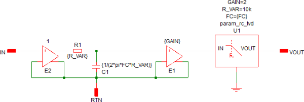
component. Result: The schematic for the param_rc_tvd_top.sxcmp schematic component opens. In addition to the single-stage filter (E1, E2, R1, C1), a second-stage filter is included using a second level of the hierarchy. The symbol for the param_rc_tvd.sxcmp schematic component filter represents the second level of the hierarchy.
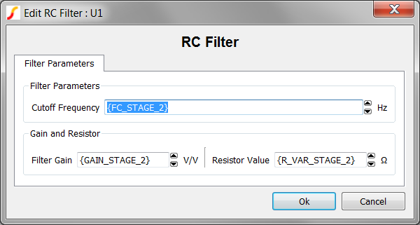
- Double click on U1, the param_rc_tvd.sxcmp schematic component.
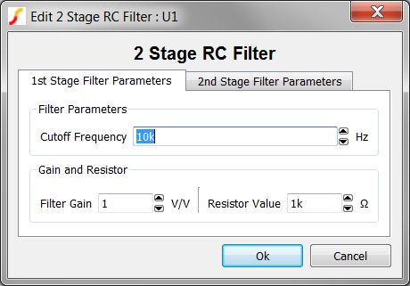
Result: The tabbed parameter-editing dialog for the RC Filter opens:
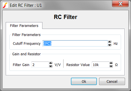 Note: The local parameter FC is passed to the second-stage filter inside the expression {FC}.
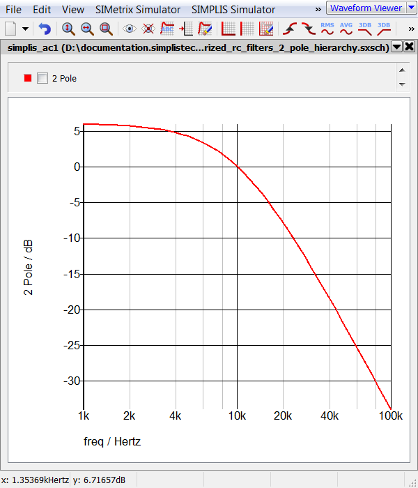
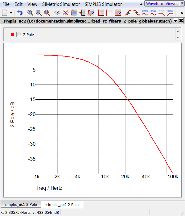
 - Press F9 to run the simulation. Result: The simulation runs as expected. The cascaded filter has two poles at 10kHz with a DC gain of 6dB.
Discussion: Exercise #1
The following describes the process that occurs in the simulation above:
- In the parameter-editing dialog for the second-stage filter U1, the parameter FC, which is local to the param_rc_tvd_top.sxcmp schematic, is assigned to the FC symbol property of the param_rc_tvd.sxcmp filter symbol.
- The symbol-to-subcircuit interface for the param_rc_tvd.sxcmp takes this symbol property value and passes the value as a parameter to the underlying schematic.
- The end result is that the FC parameters at the two different hierarchy levels are identical and equal to the value assigned to the top-level param_rc_tvd_top.sxcmp symbol.
- In this example, the two other parameters used in the param_rc_tvd.sxcmp schematic component, GAIN and R_VAR are assigned fixed values.
One of the key benefits to passing parameters explicitly through the symbol-to-subcircuit interface is that you have complete control over the parameters used at each hierarchy level and you have a modular implementation.
- The param_rc_tvd.sxcmp is a stand-alone schematic component and can be reused in any other design.
- Because parameters are passed explicitly, you can choose which parameters are passed from one level to another via the symbol-to-subcircuit interface. Fixed parameter values can be entered on the dialog.
- Where the parameters are defined is never in question - a user simply clicks on the dialog to view the parameters.
The next exercise which uses the .GLOBALVAR statement to pass parameters through the hierarchy illustrates a direct contrast to the example in Exercise #1.
Exercise #2: Using .GLOBALVAR to Promote a Local Parameter
In this exercise, you will learn how the .GLOABALVAR statement can be used to promote a local parameter to a global parameter.
- Open the schematic 5.7_parametrized_rc_filters_2_pole_globalvar.sxsch.
- Select U1, which is the two-pole RC filter.
- Press Ctrl+E to descend into the param_rc_tvd_top_globalvar.sxcmp
schematic component. Result: The schematic for the param_rc_tvd_top_global.sxcmp schematic component opens. As in the previous example, a second-stage filter is included using a second level of the hierarchy.
- Select U1, the second-stage RC filter.
- Right click and select Edit/Add Properties... from the context menu.
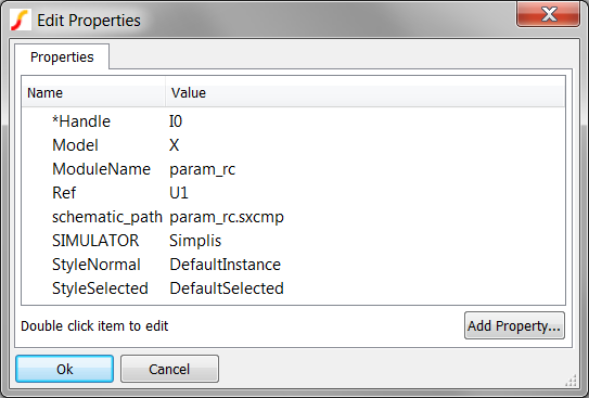
Result: The properties for the param_rc.sxcmp symbol are displayed in the Edit Properties dialog.Note: No parameter values are stored on symbol properties and no SIMPLIS_TEMPLATE property is present. This symbol does not pass parameters into the underlying schematic.
- Click Cancel on the Edit Properties dialog.
- Press F11 to open the command (F11) window for the schematic component.
Result: The two comment lines and three .GLOBALVAR statement promote the local parameters to global parameters.
*** Three parameters were passed into this level. *** Here we "promote" the parameter scope to global. .GLOBALVAR FC={FC} .GLOBALVAR R_VAR={R_VAR} .GLOBALVAR GAIN={GAIN} - Press F9 to run the simulation. Result: The simulation runs and the cascaded filter has a DC gain of 0dB because the GAIN parameter is made global at the first level, resulting in the same gain for both filters. Because the .GLOBALVAR method is used, there is no way to change this.
Discussion: Exercise #2
The following describes the process that occurs in the simulation above:
- In this example, the FC, R_VAR, and GAIN parameters are passed into the param_rc_tvd_top_globalvar.sxcmp schematic from the symbol via the symbol-to-subcircuit interface.
- These parameters are local to this schematic level and cannot be used in any sub-levels.
- The three .GLOBALVAR statements in the F11 window effectively promote these parameters to be global at this level and every level below the current level .
- Just because the parameter is promoted to a global parameter at this level does not make it available at higher levels of hierarchy, such as at 5. 7_parametrized_rc_filters_2_pole_globalvar.sxsch.
Exercise #3: GLOBALVAR Scope
This exercise demonstrates how global parameters are not available at higher levels of the hierarchy.
- Press Ctrl+U to ascend to the top level schematic: 5.7_parametrized_rc_filters_2_pole_globalvar.sxsch .
- Double click on R1 to edit the value.
- Change the Result field to {FC}as shown below:
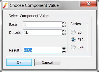
- Click Ok to accept these changes.
- Change the Result field to {FC}as shown below:
- Press F9 to run the simulation. Result: The simulation halts with an error because the parameter FC is not defined at the top level schematic.
****************************************
<<<<<<<< Error Message ID: 1038 >>>>>>>>
input file C:\Training\Module_5_Examples\SIMPLIS_Data/5.7_parametrized_rc_filters_2_pole_globalvar.deck, line 9:
    R1 9 0 {FC}

A number to represent the value
for `resistance' is expected at the
location where `{FC}' occupies.
Discussion: Exercise #3
Parameters promoted to global are available only at the level of hierarchy where the .GLOBALVAR statement is located and at lower levels. This important concept helps demonstrate that the passing of parameters between hierarchy levels is unidirectional. Parameters are always passed from higher levels to lower levels, never the other way around.
Exercise #4: Passing Parameters From the Top-Level Schematic Component
At times, you may need to pass parameters from a top-level schematic component, such as an IC, to a specific lower-level component. This example separates the parameters for the two filters and provides a top-level editing dialog for both filters.
- Open the schematic 5.8_parametrized_rc_filters_independent.sxsch.
- Double click on the symbol for U1. Result: The parameter-editing dialog opens with two tabs: one for each filter stage. The symbol has six parameters: three for the first-stage filter and three for the second-stage filter.
- Click Cancel on the dialog.
- Press Ctrl+E to descend into the param_rc_tvd_independent.sxcmp schematic.
- Double click on U1, which is the second-stage RC filter. Result: The parameter-editing dialog opens, populated with the second-stage filter parameters which are passed into the param_rc_tvd_independent.sxcmp via the symbol-to-subcircuit interface of the top-level 2 stage filter.. The second stage filter param_rc_tvd then passes these parameters into the schematic of the param_rc_tvd.sxcmp through the symbol-to-subcircuit interface.
Discussion: Exercise #4:
The two RC filters in the example above use two sets of parameters that are completely independent of each other even though the parameters are edited on the top-level symbol. The three second-stage parameters FC_STAGE_2, R_VAR_STAGE_2, and GAIN_STAGE_2 are used only in the second-stage filter although the parameter values are available on the first level as well. You can extend this method to any number of hierarchy levels. The symbol on each hierarchy level will pass all parameters which are used at lower levels.
Conclusions and Key Points to Remember
- Passing parameters through the symbol-to-subcircuit interface with the SIMPLIS_TEMPLATE symbol property provides a flexible and modular component. Because models parameterized this way are modular, they can be reused in other subcircuits. Parameter values can be passed down through the hierarchy by enclosing the local parameter in curly braces {}.
- Using the .GLOBALVAR statement to pass parameters to lower levels in the hierarchy is not a modular approach, which means that all schematic components parameterized with .GLOBALVAR have identical values. For this reason, using .GLOBALVAR should be avoided. Schematic components parameterized this way are not modular because the parameters must be defined in a higher level of the hierarchy.
Module Evaluation Form
At the end of the module, please fill out the Module # 5 Evaluation form.