Converting MOSFET SPICE Models With >3 Terminals
Many SPICE models contain more than 3 terminals to model such things as separate bulk or substrate connections or thermal characteristics. However, one of the main requirements described in Converting SPICE Models for use in SIMPLIS - Overview is the part must have only 3 terminals: the drain, the gate, and the source. Because of this, any MOSFET model that contains more than 3 terminals must be placed within a 3-terminal wrapper sub-circuit. The following 2 examples will show how this is done and can be downloaded here. To follow the examples:
In this topic:
Example 1: 4-terminal – Bulk Region
- Before moving to SIMPLIS, you will want to make sure the model simulates properly in SIMetrix. Create a test circuit and wire the device up properly. This can be found in mosfet_gt_3_terminals_L1_SIMetrix_4_pin.sxsch.
- To determine how the wrapper sub-circuit should be wired, refer to the following schematic:
Figure: L1 Wrapper Sub-circuit
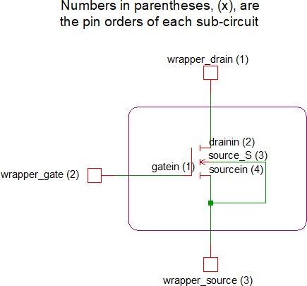 Note: This schematic shows two useful pieces of information: the pin orders of the wrapper sub-circuit and original sub-circuit as well as the necessary internal connections.
 - Open original_GaN_PSpice_GS66502B_L1V4P1.txt in a text editor and make the
following changes:
- Add the .subckt line for the wrapper, which is the first line of the
wrapper sub-circuit definition. This definition needs to have a unique subcircuit
name and the same pin order as the SIMPLIS MOSFET symbol (Drain, Gate,
Source):
.subckt GaN_SIMPLIS_GS66502B_L1V4P1 wrapper_drain wrapper_gate wrapper_source
- Add a model-library category and symbol association line. For N-Channel MOSFETs,
you can copy the special comment line below and paste it immediately following the
.subckt line of the wrapper
subcircuit:
*#ASSOC Category=NMOS Symbol=nmos_sub
For devices other than N-Channel MOSFETs, use the table at the bottom of the topic named Converting SPICE Models for use in SIMPLIS - Overview.
- Add the instantiation line of the original sub-circuit
device:
X1 wrapper_gate wrapper_drain wrapper_source wrapper_source GaN_PSpice_GS66502B_L1V4P1
- "X1" denotes a sub-circuit
- "wrapper_gate wrapper_drain wrapper_source wrapper_source" are the wrapper sub-circuit nodes being connected to the proper nodes of the original sub-circuit. Note, the pin order of the original Spice model differs from the pin order of the wrapper subcircuit. Also, the source pin of the wrapper subcircuit is connected to both the source and bulk connector of the original sub-circuit
- "GaN_PSpice_GS66502B_L1V4P1" points to the original sub-circuit model
- Add the .ends line for the wrapper
sub-circuit:
.ends GaN_SIMPLIS_GS66502B_L1V4P1
- Save the text file
Result: You have now created a new MOSFET Spice model that has only three terminals and is now compatible with the SIMPLIS MOSFET model extraction process.The resulting file is the same as what is shown in final_GaN_PSpice_GS66502B_L1V4P1.txt, minus the comment lines. - Add the .subckt line for the wrapper, which is the first line of the
wrapper sub-circuit definition. This definition needs to have a unique subcircuit
name and the same pin order as the SIMPLIS MOSFET symbol (Drain, Gate,
Source):
- Rebuild the model library by using the menu item.
- Create a SIMetrix Spice schematic to test the new sub-circuit. An example can be found in mosfet_gt_3_terminals _L1_SIMetrix_3_pin.sxsch.
- Once you have verified that your new 3-terminal device works in SIMetrix, create a SIMPLIS schematic to test the SIMPLIS MOSFET model extraction process. An example can be found in mosfet_gt_3_terminals_L1_SIMPLIS.sxsch.
Example 2: 6-terminal – Bulk Region and Thermal Network
This example will demonstrate a more complex case where the MOSFET Spice model has an extra terminal for the bulk region (i.e., substrate) electrical connection and two extra terminals to model thermal characteristics (i.e., junction and case temperature).
- Before moving to SIMPLIS, you will want to make sure the model simulates properly in SIMetrix Spice. Create a circuit and wire the device up properly. This can be found in mosfet_gt_3_terminals_L3_SIMetrix_6_pin.sxsch.
- To determine how the wrapper sub-circuit should be wired, refer to the following schematic:
Figure: L3 Wrapper Sub-circuit
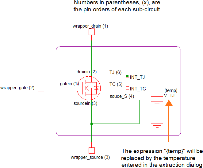 Note: This schematic shows four useful pieces of information: the pin orders of the wrapper and original sub-circuits, the electrical connection to the bulk region, the thermal network connections, the as well as the necessary internal connections between the wrapper subcircuit and the original 6-pin model.
 - Open original_GaN_PSpice_GS66502B_L3V4P1.txt in a text editor and make the
following changes:
- Add the .subckt line of the wrapper sub-circuit definition. This definition
needs to have a unique name and the same pin order as the SIMPLIS MOSFET symbol
(Drain, Gate,
Source):
.subckt GaN_SIMPLIS_GS66502B_L1V4P1 wrapper_drain wrapper_gate wrapper_source
- Add a model-library category and symbol association line. For N-Channel MOSFETs, you
can copy the special comment line below and paste it immediately following the
.subckt line of the wrapper
subcircuit:
*#ASSOC Category=NMOS Symbol=nmos_sub
For devices other than N-Channel MOSFETs, please refer to the table at the bottom of the topic named Converting SPICE Models for use in SIMPLIS - Overview.
- Add an instantiation line for the voltage source that sets the Junction
Temperature
V_TJ INT_TJ 0 {temp}- "V_TJ" denotes a voltage source that will be set to a value equal to the estimated junction temperature
- "INT_TJ 0" connects the positive terminal of the voltage source between the INT_TJ node and ground
- "{temp}" sets the voltage of the voltage source. Using the expression will allow you to define the junction temperature of the Spice model to be equal to the temperature entered in to the Extract MOSFET Parameters dialog
- Add the instantiation line of the original sub-circuit
device:
X1 wrapper_gate wrapper_drain wrapper_source wrapper_source INT_TC INT_TJ GaN_PSpice_GS66502B_L3V4P1
- "X1" denotes a sub-circuit
- "wrapper_gate wrapper_drain wrapper_source wrapper_source INT_TC INT_TJ" connect the wrapper sub-circuit nodes to the proper nodes of the original sub-circuit. Note, the pin order of the original 6-terminal Spice model differs from that of the wrapper subcircuit. Also, the source pin of the wrapper sub-circuit is connected to both the source and bulk connector of the original sub-circuit
- "GaN_PSpice_GS66502B_L3V4P1" points to the original sub-circuit model
- Add the .ends line for the wrapper
sub-circuit:
.ends GaN_SIMPLIS_GS66502B_L3V4P1
- Save the text file
Result: You have now created a new MOSFET Spice model that has only three terminals and is now compatible with the SIMPLIS MOSFET model extraction process. The resulting file is the same as what is shown in final_GaN_PSpice_GS66502B_L3V4P1.txt, minus the comment lines. - Add the .subckt line of the wrapper sub-circuit definition. This definition
needs to have a unique name and the same pin order as the SIMPLIS MOSFET symbol
(Drain, Gate,
Source):
- Rebuild the model library by using the menu item.
- Create a SIMetrix Spice schematic to test the new sub-circuit. An example can be found in mosfet_gt_3_terminals_L3_SIMetrix_3_pin.sxsch.
- Once you have verified that your new 3-terminal device works in SIMetrix, create a SIMPLIS schematic to test the SIMPLIS MOSFET model extraction process. An example can be found in mosfet_gt_3_terminals_L3_SIMPLIS.sxsch.