Arbitrary Source
In this topic:
Netlist Entry
Bxxxx n+ n- [MIN=min_value] [MAX=max_value] V=expression
Bxxxx n+ n- [MIN=min_value] [MAX=max_value] [M=multiplier] I=expression
Bxxxx n+ n- [M=multiplier] Q=expression
Bxxxx n+ n- FLUX=expression
An arbitrary source is a voltage or current source whose output can be expressed as an arbitrary relationship to other circuit voltages or currents.
| expression | Algebraic expression describing voltage or current output in terms of circuit nodes or sources. See for full details. |
| min_value | Minimum value of source |
| max_value | Maximum value of source |
| multiplier | Scale factor. Source will behave as if there multiplier devices in parallel |
| Bxxxx | Component reference |
| n+ | Positive output node. |
| n- | Negative output node. |
The small-signal AC behaviour of the non-linear source is a linear dependent source with a proportionality constant equal to the derivative (or derivatives) of the source at the DC operating point.
Note that if MIN and/or MAX parameters are specified, they must precede the defining expression.
Charge and flux sources implement capacitors and inductors respectively. See charge and Flux Devices for details.
If the source is a current, the direction of flow is into the positive node (n+).
Notes on Arbitrary Expression
It is essential that the expression used for an arbitrary source is well conditioned. This means that it must be valid for all values (i.e. from ???MATH???-\infty???MATH??? to ???MATH???+\infty???MATH???) of its input variables (i.e. circuit voltages and currents) and that it is continuous. It is also desirable - although not always absolutely necessary - for the function to be continuous in its first derivative; i.e. it does not have any abrupt changes in slope.
A badly designed expression will lead to poor convergence, non-convergence or slow run times. This is especially the case if the source is used in a feedback loop. If the arbitrary source is used open loop then the above conditions can sometimes be relaxed especially if the input signal is well defined e.g. derived directly from a signal source.
Some functions are not continuous in nature. E.g. the STP() and SGN() functions are not. These may nevertheless be used in an expression as long as the end result is continuous.
IF(v1>v2, 0, (v1-v2)*2)
When v1=v2 both true and false values equate to zero so the function has no abrupt change. The function still has a discontinuous first derivative with respect to both v1 and v2 which is still undesirable but will work satisfactorily in most situations.
IF(v1>v2, 0, 5)
The result of this will switch abruptly from 0 to 5 when v1=v2. This is not something that the simulator can be guaranteed to handle and cannot be implemented in real life.
(TANH((v2-v1)*factor)+1)*2.5+2.5
where factor is some number that determines the abruptness of the switching action. For a value of 147, 95% of the full output will be achieved with just 10mV overdrive.
IF(v1>v2, 0, 5, 1e9)See IF() Function for further details.
Charge and Flux Devices
B1 n1 n2 Q = C*V(n1,n2)
B1 n1 n2 flux = L * i(B1)
The main benefit of this feature is that it makes it possible to define non-linear capacitors and inductors directly. It is also possible to use the ddt() and sdt() functions to create capacitors and inductors using regular current and voltage sources. However, the above method is more efficient.
Bprimary   p1 p2 flux = Lp*i(Bprimary)   + M*i(Bsecondary)
Bsecondary s1 s2 flux = Ls*i(Bsecondary) + M*i(Bprimary)
Arbitrary Source Examples
Example 1 - Ideal Power Converter
This examples also demonstrates the use of expressions within subcircuits (see Using Expressions).
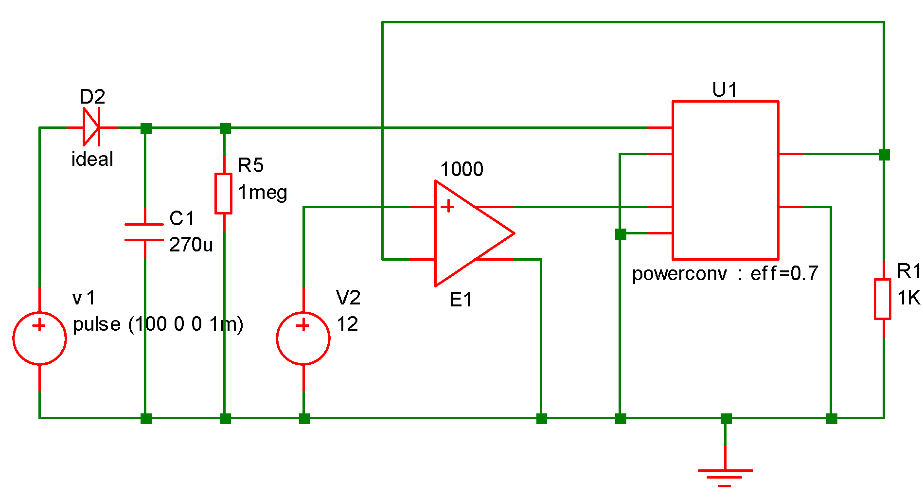
The following subcircuit implements an idealised power converter with an efficiency of eff and whose output voltage is proportional to the input voltage (vinn,vinp) multiplied by the control voltage (vcp,vcn). It is intended to simulate the voltage/current characteristics of a switching power converter.
.subckt powerconv voutp voutn vinp vinn vcp vcn
biin1 vinp vinn i=-v(voutp,voutn)/v(vinp,vinn)*i(vout1)/{eff}
vout1 bmult1_n voutn 0
bmult1 voutp bmult1_n v=v(vinp,vinn)*v(vcp,vcn)
r1 vcp vcn 1meg
.ends
Once again, with an appropriate schematic symbol, the device can be placed on the schematic as a block as shown below:
Example 2 - Voltage Multiplier
The expression for an arbitrary source must refer to other voltages and/or currents on the schematic. Currents are referenced as voltage sources and voltages as netnames. Netnames are usually allocated by the netlister. For information on how to display and edit the schematic's netnames, refer to Displaying Net and Pin Names.
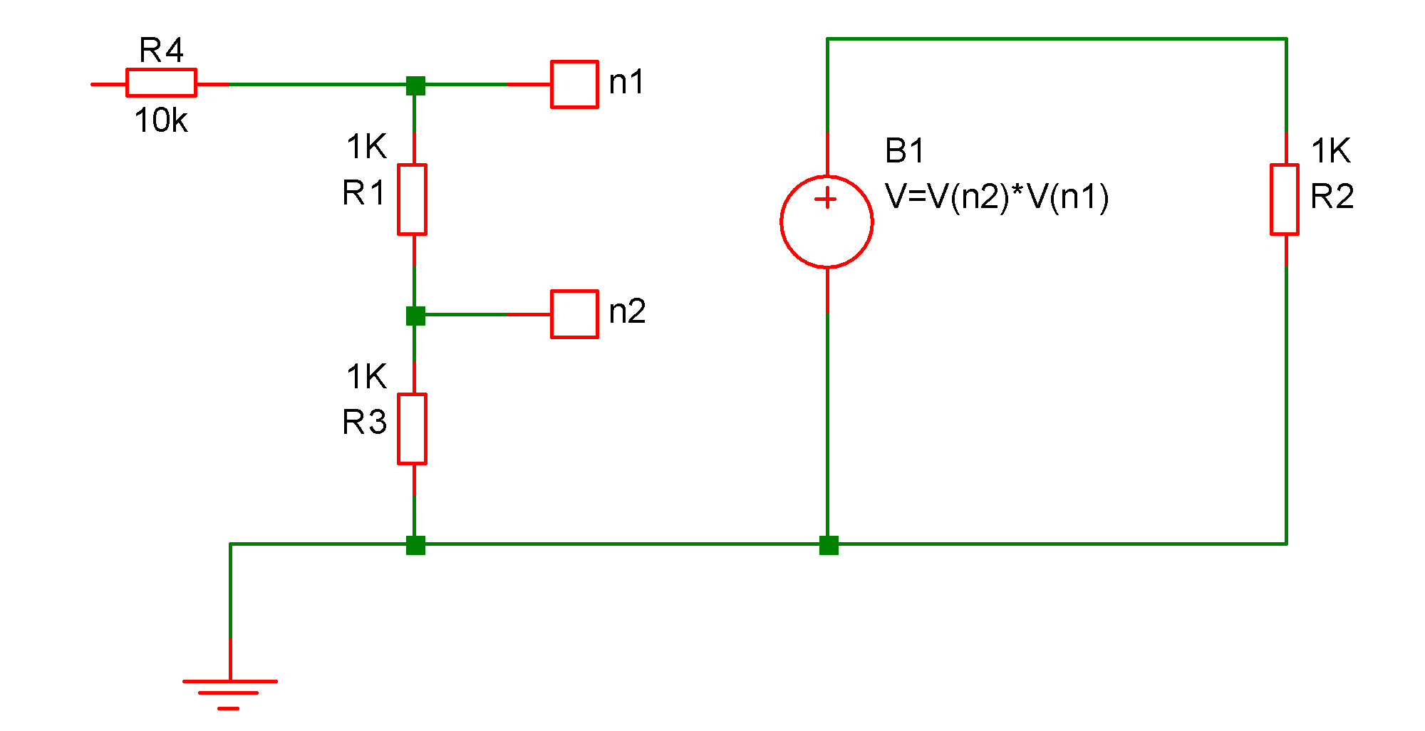
In the above circuit the voltage across B1 will be equal to the product of the voltages at nodes n1 and n2.
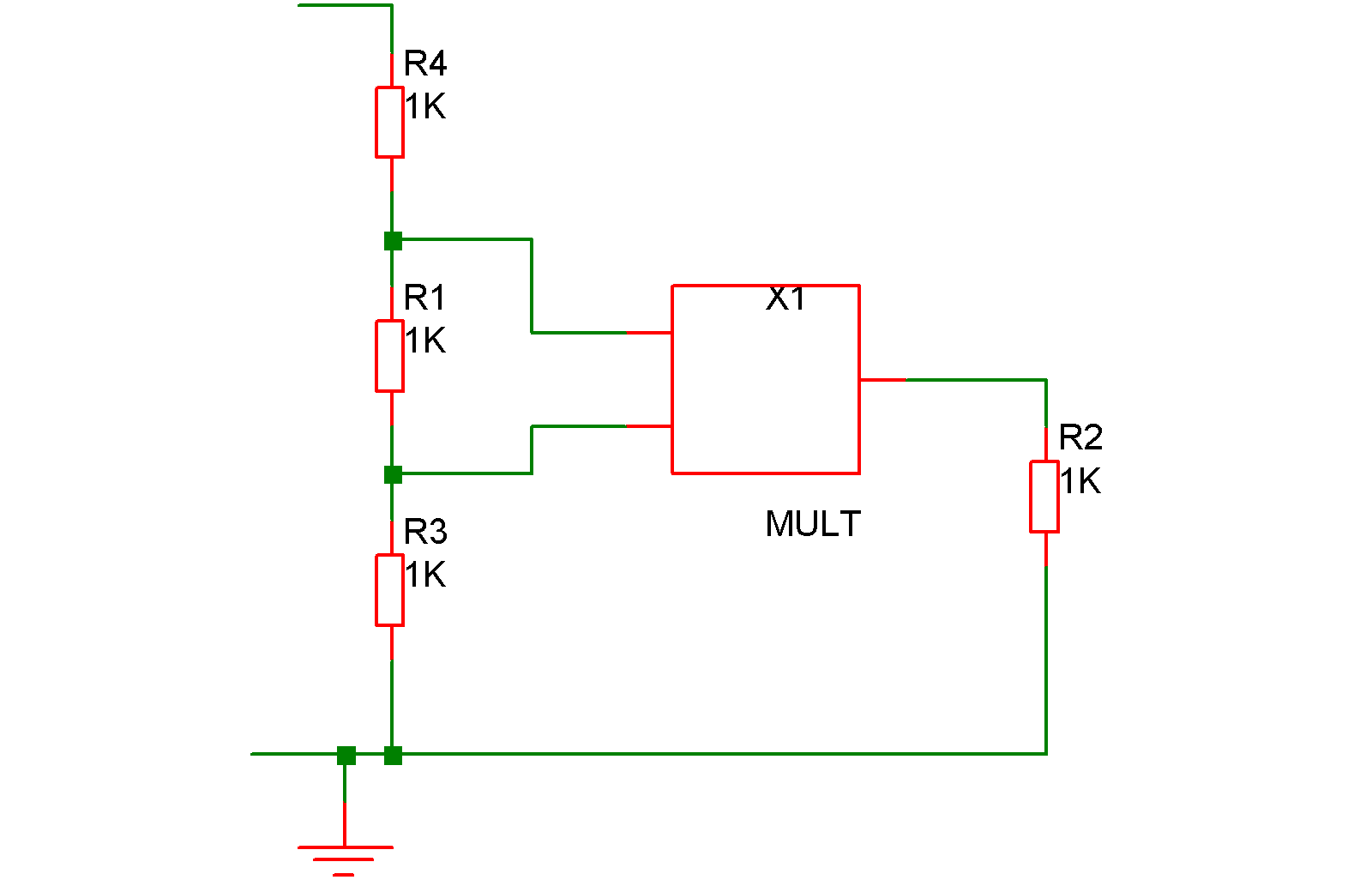
.subckt MULT out in1 in2
B1 out 0 V=V(in1)*V(in2)
.ends
which can be added to the netlist manually. (To find out how to add additional lines to the netlist when using the schematic editor, refer to Adding Extra Netlist Lines). A symbol could be defined for it and then placed on the schematic as a block as shown below:
Example 3 - Voltage comparator
B3 q3_b 0 V=atan(V(n1,n2)*1000)
This can also be added to the schematic in the same way as for the multiplier described above.
PSpice and Hspice syntax
SIMetrix supports the PSpice® and Hspice® syntax for arbitrary sources. This is for compatibility with some manufacturers device models. For PSpice® the VALUE = and TABLE = devices are supported and for Hspice® VOL= and CUR= are supported.
| ◄ AC Table Lookup (including S-Parameters) | Bipolar Junction Transistor (SPICE Gummel Poon) ▶ |