Tutorial
To demonstrate the basic features of Verilog simulation, we will work through the trivial example shown below:
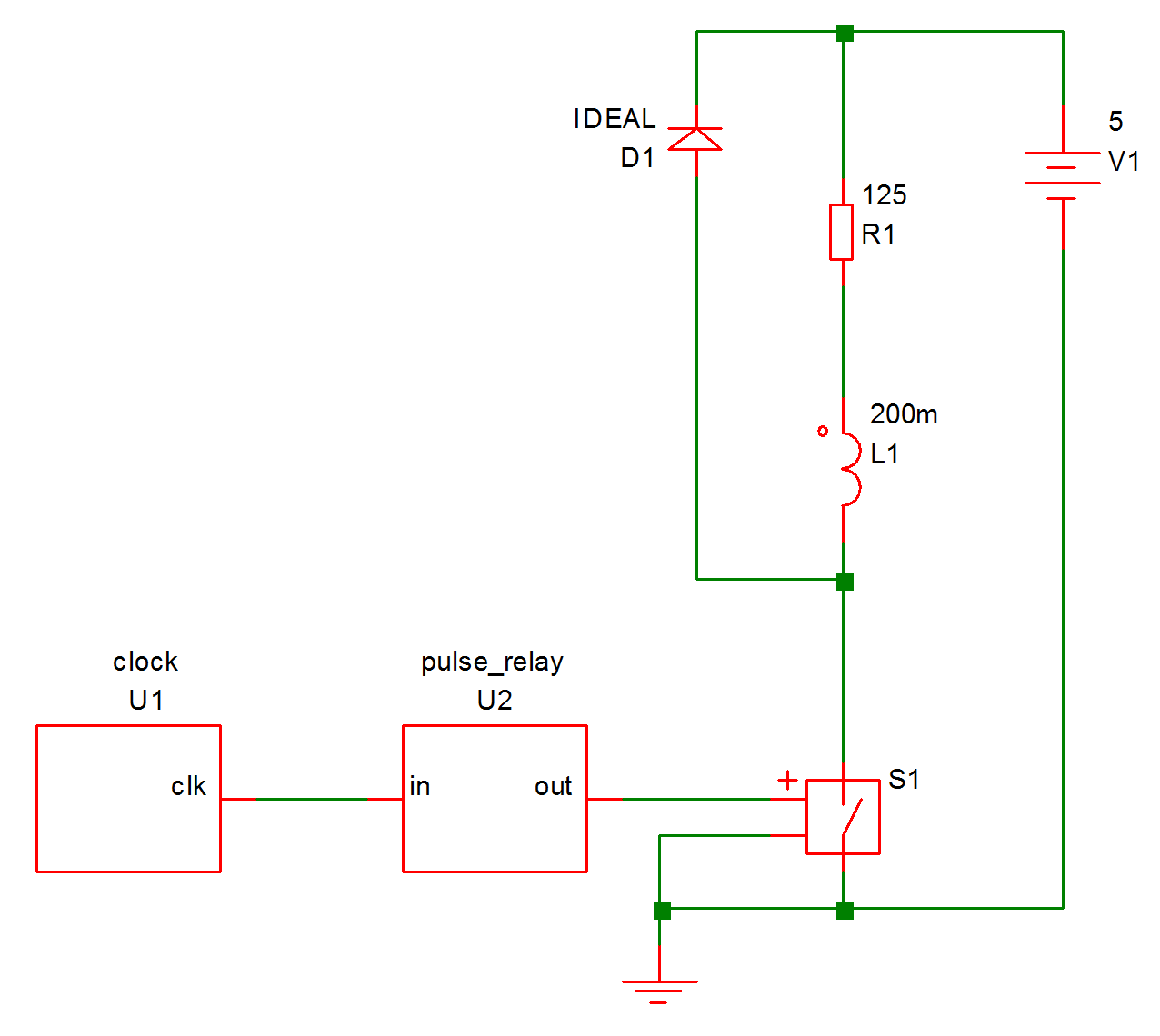
This circuit pulses a relay for 10mS every 100mS driven by a 100kHz clock. The relay coil is modelled by L1 and R1 while D1 is a freewheel diode. S1 is the relay driver and is controlled by the output of U2. This is a simple counter implemented using the following Verilog code:
module pulse_relay(in, out) ;
input in ;
output out ;

integer count ;
reg out ;

parameter divide_ratio=10000 ;
parameter real duty = 0.1 ;

always @(posedge in)
begin
count = count + 1 ;

if (count==divide_ratio)
count = 0 ;

if (count>divide_ratio*(1-duty))
begin
out = 1 ;
end else begin
out = 0 ;
end
end

initial
count = 0 ;
endmodule
The Verilog files as well as a completed working schematic can be found in Examples/Verilog-HDL/Tutorial.
In this topic:
Procedure
The following assumes that you are already familiar with the basics of entering a schematic and running a simulation.
Enter Schematic
- Open a new empty schematic sheet.
- Immediately save the empty sheet to: Examples/Verilog-HDL/Tutorial/relay-driver.sxsch In general it is strongly advised to save the schematic sheet before using the automatic Verilog symbol generation scheme that we are about to demonstrate. This is to ensure that the file system paths of the schematics and Verilog files are kept correctly synchronised.
- Select menu . You should see the file clock.v listed. If so select it then click Open. If you don't see the file, make sure you saved the schematic to the correct location in step 2 above. If you find that this menu is not present, then this means that the Verilog simulation facility is not available with your version of SIMetrix. You will probably need to upgrade your license, contact sales or support for assistance.
- You should see an image of a symbol appear. Place on schematic in the usual way.
- Repeat step 3 for pulse_relay.v
- Double click the pulse_relay device (probably U2). You will see a dialog box showing a number of parameters. We aren't going to change any settings, this is just to point out this feature. You should see two parameters at the bottom of the top section called 'divide_ratio' and 'duty'. These are obtained from the Verilog file pulse_relay.v.
- Connect the rest of the circuit as shown in the diagram above. S1 is a regular switch from menu . Make sure you don't forget the ground symbol.
Set up Simulation
- Set up a 200mS transient analysis in the usual way
- Select Gear integration using menu then click on Advanced Options... and select Gear Integration under the Integration Method group. We do this to tidy up the response of the circuit, this is by no means essential.
Run Simulation
- Run the simulation in the usual way. It should take about 1-2 seconds maybe a little longer on an older machine.
-
Plot the voltage on the relay coil. You should see something like this:
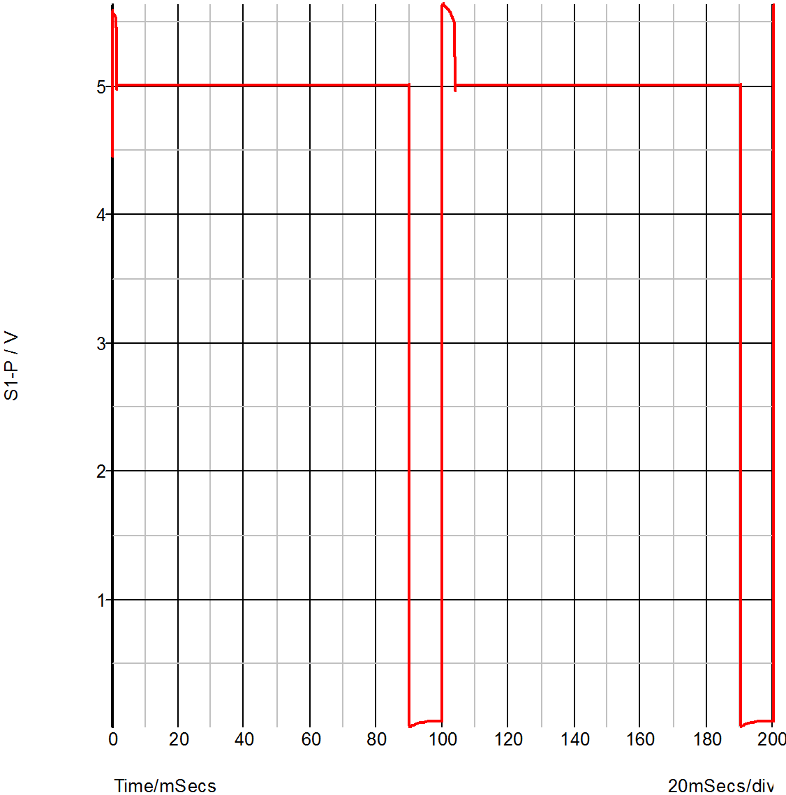 You will notice that at t=0, the voltage is between 4 and 5 volts suggesting that the switch is not fully turned on or off. This is because the output of U2 starts in the unknown state. The unknown state is translated to a high-impedance which leaves the output in a near floating state. To calculate the DC operating point, SIMetrix takes the port values after the first Verilog event which is the state after executing the init block. In the Verilog design the output is the port but you will notice in pulse_relay.v that is not defined in the init block.
-
Modify the pulse_relay.v to add an initial definition for the port as follows:
initial
begin
count = 0 ;
out = 0 ;
end
- Rerun the simulation and notice the change in the result at the start of the simulation.
Internal Verilog Nodes
Have a look at the connection between U1-clk and U2-in. This connects two Verilog signals but does not connect to any analog part. Because of this, it is implemented within the Verilog simulator and does not interact with the analog simulator.
Although the node is not connected to the analog simulator, its data is sent to SIMetrix so that it can be plotted. Try plotting this node now; you will notice that you get a digital plot with no analog detail.
Although, SIMetrix does retrieve the data for internal verilog nodes that interconnect VSXA instances, in circuits where the Verilog digital signals are much higher speed than the analog signals - such as this example - there is a speed penalty for doing so. For this reason there is a facility to disable this. To demonstrate, proceed as follows:
- Note the time that the last run took using menu
-
Double click U1 (the instance of clock.v). You should see a dialog box like this:
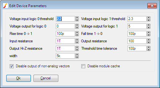
- Check the Disable output of non-analog vectors box then click Ok.
- Rerun simulation and note the new simulation time. You will probably see in the region of a 2-3 times speed up. You may conclude from this that the facility to retrieve pure digital data is too expensive to be worthwhile, but this will only be the case where the digital signal are considerable higher speed than the analog signals. In this circuit the analog pulses are running at 10Hz whereas the digital pulses are running at 100kHz - 10000 times as fast.
- As a further exercise, you may like to see what happens when this node is connected to an analog part. Try connecting a 1pF capacitor to ground and run the simulation. You will find that the simulation runs maybe 100 times slower. This is because analog time steps is now being performed for this high frequency signal. With just the 10Hz output to deal with, the analog simulator needed to perform only around 200 timepoints. Now it has to work at 100KHz it needs 1 million or so.
Multi-step Run
As a final exercise, we will show how it is possible to perform multi-step runs while varying a parameter sent to a Verilog device. We will run a 3 step simulation while varying the DUTY parameter of the pulse_relay device. Proceed as follows:
- Double click U2
-
Set the 'duty' parameter to:
{duty} - Open the choose analysis dialog box.
- In the Transient sheet, select Enable multi-step then click Define.
- In Sweep mode select Parameter. Set Start value and Stop value to 100m and 500m respectively. Set Number of steps to 3.
- In Parameters set Parameter name to duty.
- Ok dialog boxes. If you carried out step 5 in the previous section Internal Verilog Nodes, remember to remove the capacitor and restore the connection between U1 and U2 to an internal Verilog node.
- Run simulation then plot relay drive as before. You should see three curves.
| ◄ Simulation Options | Verilog Simulator Interface ▶ |