Subcircuits
In this topic:
Overview
Subcircuits are a method of defining a circuit block which can be referenced any number of times by a single netlist line or schematic device. Subcircuits are the method used to define many device models such as op-amps. It is also the underlying mechanism of the hierarchical schematic entry system.
You don't need to know anything about subcircuits unless you wish to define you own device models, perhaps to build up a library of tested blocks for general distribution. If you just wish to enter your circuit in a modular manner, hierarchical schematic entry is probably the more appropriate method. See Hierarchical Schematic Entry for details.
This section explains how to create a subcircuit from a schematic and how to reference one in netlist or schematic. For the .SUBCKT control syntax see the "Command Reference" chapter of the Simulator Reference Manual.
Creating a Sub-circuit from a Schematic
Subcircuits must be defined in text form as a netlist. However the schematic editor can be used to generate the netlist. To create a sub-circuit from a schematic, you need to identify which nodes are to be connected externally. This is done using the same Module Port symbol used for hierarchical schematic entry (see Hierarchical Schematic Entry).
The procedure for defining a subcircuit is as follows:
- Draw circuit using schematic editor including module port symbols to identify external connections.
- Create netlist for circuit.
Stage 1 - Draw Schematic
This is circuit of a simple op-amp. In fact it is the circuit of our fictitious SXOA1000 op-amp used in Tutorial 3.
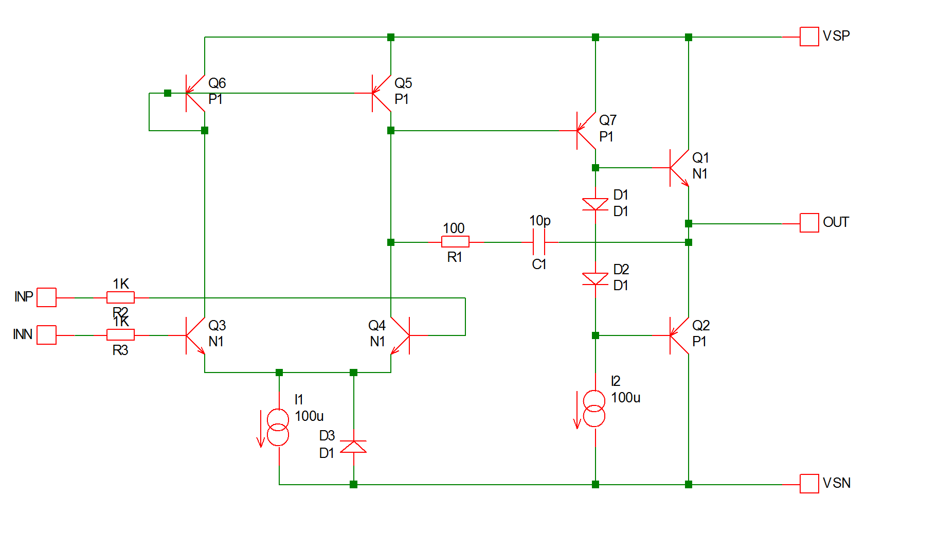 The five terminal symbols, e.g.

are the connections to the outside world. This is a module port symbol which can be found in the schematic menu . Important - do not use the normal Terminal symbol.
It is recommended that any model definitions are included in the subcircuit definition. This makes the subcircuit self-contained. If you have referenced models in the device library, you can import them into the schematic automatically using the schematic menu They will be placed in the simulator command window which can be opened by pressing F11. Alternatively you can enter them in the command window manually.
Stage 2 - Netlist Circuit
To create a subcircuit netlist, select schematic menu .
You will be first be prompted for a subcircuit name. This name will also be used for the file name with extension .MOD.
After entering the name, you will be asked to specify the subcircuit pin order:
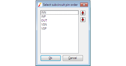
When you close this box, the subcircuit will be created and its text will be displayed.
Calling a Sub-circuit in a Schematic
To call a sub-circuit in a schematic, you must choose or create a symbol for it. The symbol must have the same number of pins and, ideally, it would also have the same pin order. In other words, the order of the nodes in the .SUBCKT line would be the same as the pin order of the symbol. The matching of .SUBCKT node order and symbol pin order is not absolutely essential, but it makes things much easier. If they are not the same there is method of overcoming the problem using the mapping property. This is explained in the section Properties.
Creating symbols for the schematic is covered in Creating Schematic Symbols - Overview. The symbol must have the following properties (see Properties).
| Property name | Property value | Purpose |
| Model | X | Ensures netlist line starts with X. Identifies part as a subcircuit. Should be hidden and protected |
| Value | subcircuit_name | Name used to reference subcircuit definition. Can be changed by user after placing on schematic. |
| Ref | component_reference | E.g. U?. Automatically allocated when placing symbol on schematic. |
To use the sub-circuit definition, SIMetrix must be able to find it. There are various places where it can be put and means of telling SIMetrix of the location. These are the choices.
- Place the definition directly in the simulator command - or F11 - window (see Manual Entry of Simulator Commands). If placed at that location, it will be read in unconditionally and SIMetrix will not need to search for it.
- Put in a separate file and pull in to the schematic with .INC control (see Simulator Reference Manual/Command Reference/.INC) placed in simulator command (F11) window. As 1., this will be read in unconditionally.
- Put in a library file and reference in schematic with .LIB control (see Simulator Reference Manual/Command Reference/.LIB) placed in simulator command (F11) window. Similar to 2. but more efficient if library has many models not used in the schematic. Only the devices required will be read in.
- Put in a library file and install it using the procedure described in Full Model Installation Procedure. This will make the device globally available to all schematics. You can also install it into the model library browser system. These topics are covered in Device Library and Parts Management and are also the subject of Tutorial 3.
If you installed the device into the model library browser system, as mentioned in choice 4 above, you will be able to place the device by pressing control-G and selecting the device from the appropriate category. The model library browser system also provides a simple to use means of overcoming the problem mentioned above that occurs if the symbol's pin order does not match the subcircuit's node order. This is explained in Associating Multiple Models with Symbols.
Passing Parameters
You can pass parameters to a subcircuit. This subject is covered in detail in the Simulator Reference Manual/Simulator Devices/Subcircuits/Passing Parameters to Subcircuits. To specify the parameters for a sub-circuit device in a schematic, you must enter the values manually using Shift-F7. Enter the values after the subcircuit name. E.g. suppose you wished to specify the parameters: 'FREQ=12k Q=15'. To enter these, select the sub-circuit, press shift-F7 and append the sub-circuit name with:
FREQ=12k Q=15
You can add 'params:' to emphasise where the parameters start and also for compatibility with some other simulators. E.g:
params: FREQ=12k Q=15
Note for information about passing parameters to a hierarchical block, please refer to Passing Parameters Through a Hierarchy.
| ◄ Creating Models | Special Parts ▶ |