Multi-Step Analysis
The DVM Multi-Step Analysis allows you to step a set of design parameters over a range of values using a decade-step or linear-step sequence. You may also step values over a defined list of parameter values. One advantage of using a single test with a multi-step analysis over multiple DVM tests is the multi-core capability which is part of the Pro and Elite license packages. The multi-core capability runs steps in parallel on multiple processor cores and will greatly reduce the simulation time required for the multi-step analysis. Even using a single processor core reduces the required simulation time as the schematic is setup once, as is the graph and data collection after the simulation completes.
The Multi-Step Analysis doesn't determine the actual simulation Objective nor the POP, AC or TRAN Analysis directives, rather, the Multi-Step Analysis specifies that the configured analysis is to be run through one or more parameter steps. The Multi-Step Analysis is configured using an Analysis testplan entry.
In this topic:
Multi-Step Parameter Definition
The table on the Multi-Step Analysis page allows you to enter the parameter names and their associated step parameters. The dialog allows you to configure three different step modes:
- A Linear step where the parameter is stepped from the Start Value to the Stop Value using the Number of Steps in a linearly spaced sequence. The number of steps run will always be the parameter entered into the Number of Steps field.
- A Decade step where the parameter is stepped from the Start Value to the Stop Value using the Number of Steps per decade in a logarithmic sequence. The total number of steps depends on the Start Value, Stop Value, and the Number of Steps.
- A List sequence where the parameter is stepped over a user-defined list of parameter values. There are no restrictions on the values of the list. The total number of steps depends only on the number of values entered.
To enter parameter step information, follow these steps:
- Enter a parameter name in the Parameter Name column.
- Select the desired Step Type from the drop-down list. After you select the step type, the rest of the valid controls for this parameter are enabled.
- For List step types, enter the list of values by double clicking on the List Values table cell or click on the Define List... button.
| Table Column | Description |
| Parameter Name | The name of the stepped
parameter. The schematic symbols should be parameterized with this
parameter name using braced {} substitutions as shown at the top of the
dialog image above. Note: You can automatically change symbol property
values by using the Change testplan entry.
|
| Step Type | The step type can be one of
the following:
|
| Start Value | The starting value for the parameter step, used with decade and linear steps |
| Stop Value | The ending value for the parameter step, used with decade and linear steps |
| Number of Steps | The number of steps for the decade or linear steps. For decade steps, this parameter value is the number of steps per decade, for linear steps, the parameter value is the number of equally spaced steps. |
| List Values | The list of stepped values. This cell is automatically populated by the dialog opened with the Define List... button. |
Additional parameters can be stepped by clicking on the Add... button and individual parameters can be removed with the Remove... button. The total number of steps is the product of number of steps for each stepped parameter. The total number of steps is calculated and shown below the table in the Total number of steps text.
| Multi-core | |
| Number of cores | The number of cores used for the simulation. The Pro and Elite licenses allow the use of 4 and 16 cores respectively. |
| Save state | If checked, SIMPLIS will save initial conditions files with names which reflect the stepped parameter values. You can use the GenerateInitFile entry to save the initial conditions files and the IncludeInitFile entry to include these files. |
For more information on the multi-step analysis see the Advanced SIMPLIS Training topic: 3.1 Multi-Step Simulations.
Testplan Syntax
The multi-step analysis has three configurations, each of which is entered in an Analysis column.
- The first configuration has no arguments and uses all parameters entered on the dialog described above.
- The second configuration steps an individual parameter over the defined step sequence.
- The third configuration steps an individual parameter and includes an optional parameter string.
The Multi-Step analysis has the following syntax with the arguments described in the table below:
| Analysis |
|---|
| Multi-Step |
| Multi-Step( PARAM_NAME, STEP_TYPE, NUM_STEPS, START_VALUE, STOP_VALUE ) |
| Multi-Step( PARAM_NAME, STEP_TYPE, NUM_STEPS, START_VALUE, STOP_VALUE, OPTIONAL_PARAMETER_STRING ) |
| Argument | Range | Description |
| PARAM_NAME | n/a | The name of the stepped parameter. The schematic symbols should be parameterized with this parameter name in braced {} substitutions. You can automatically change values using the Change testplan entry. |
| STEP_TYPE |
|
The step
type can be one of the following:
|
| NUM_STEPS | n/a | The number of steps for the decade or linear steps. |
| START_VALUE | n/a | The starting value for the parameter step, used with decade and linear steps. |
| STOP_VALUE | n/a | The ending value for the parameter step, used with decade and linear steps. |
| OPTIONAL_PARAMETER_STRING | n/a | Two
additional parameter can be entered as a key=value pairs on the
OPTIONAL_PARAMETER_STRING. The two optional parameters are:
|
LIST Step Type
The LIST step type uses a variable length function call as described below. Every value after the PARAM_NAME and LIST arguments is interpreted as a parameter value to be stepped. The same OPTIONAL_PARAMETER_STRING options can be used with the LIST step type.
| Analysis |
|---|
| Multi-Step( PARAM_NAME, LIST, VAL1, VAL2, VAL3, ..., VALN ) |
| Multi-Step( PARAM_NAME, LIST, VAL1, VAL2, VAL3, ..., VALN , OPTIONAL_PARAMETER_STRING ) |
Where VAL1, VAL2, VAL3 ... VALN are the stepped parameter values.
Stepping Multiple Parameters
Beginning with version 8.10, multiple parameter steps can be defined using the DVM Control Symbol dialog. To use the parameters defined in the DVM Control Symbol dialog, simply add an analysis column to an existing testplan and enter Multi-Step in the test row for this column. You can also define and step additional parameters using additional analysis columns. Each additional analysis column defines a new parameter step. Some examples will be helpful to understand how multiple analysis columns work.
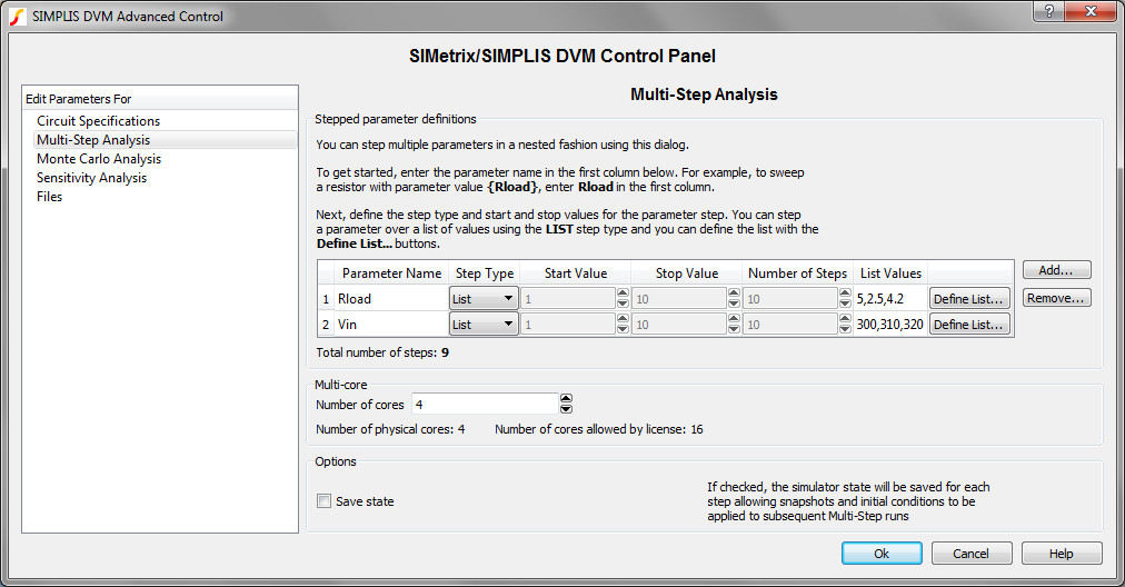
In the DVM Control Dialog, two parameters, RLoad and Vin are defined with 5 and 3 stepped values respectively.
- The first test uses the Analysis testplan entry Multi-Step, which instructs DVM to use the multi-step parameters saved to the DVM control symbol, in this example, RLoad and Vin. This test steps RLoad over a list of values (5, 2.5, 4.2), and Vin over a Linear step sequence from 300 to 320 with 3 steps. These parameter values were saved to the DVM control symbol. A total of 9 (3*3) simulations are run.
- The second test uses two analysis columns, the first with the entry: Multi-Step sets up a multi-step simulation using the DVM control symbol parameters, as above. The second column, with entry Multi-Step( L4_Tol, Linear, 3, 0.95, 1.05 ) adds the parameter step L4_Tol over a linear step sequence from 0.95 to 1.05 to the DVM control symbol defined parameters. A total of 27 (3*3*3) simulations are run.
- The third test defines three parameters in three analysis columns. The parameters defined on the DVM control symbol are not used because no analysis column has the Multi-Step keyword. Only the testplan-defined multi-step parameters are used in the multi-step simulation.
| *** | ||||
|---|---|---|---|---|
| *** multi-step_power_assist.testplan | ||||
| *** | ||||
| *?@ Analysis | Analysis | Analysis | Objective | Label |
| **** | ||||
| Multi-Step | steady-state | Multi-Step|Uses Control Symbol Values | ||
| Multi-Step | Multi-Step( L4_Tol, Linear, 3, 0.95, 1.05 ) | steady-state | Multi-Step|Control Symbol Steps Plus a Testplan Defined Step | |
| Multi-Step( RLoad, List, 5, 4.2, 2.5 ) | Multi-Step( Vin, Linear, 3, 310, 330 ) | Multi-Step( L4_Tol, Linear, 3, 0.95, 1.05 ) | steady-state | Multi-Step|Testplan Defined |
Changing Control Symbol Property Values Using Load Component Values
There are cases where you may want to step a completely different set of parameter values from one test to another. One way to do this is to use multiple analysis columns in the testplan as is done with the last test in the above example. Another method is to change the DVM control symbol stepped parameter values on a test by test basis using a LoadComponentValues testplan entry. Each test uses a single analysis column with the basic Multi-Step testplan entry. Each test also has a LoadComponentValues entry placed prior (to the left of in the testplan) the analysis entry. The benefits to this method lay in consolidating all schematic changes in a single file. The built-in Efficiency testplan generator included in version 8.20 and newer uses this method. You can run the testplan generator using the menu.
| *?@ LoadComponentValues | Analysis | Objective | Label |
|---|---|---|---|
| lcv\LTC3406B - DVM ADVANCED_efficiency_change.compvalues.txt | Multi-Step | Steady-State | Efficiency|Run Multi-Step Efficiency Simulation |
| lcv\LTC3406B - DVM ADVANCED_efficiency_reset.compvalues.txt | NoSimulation | Efficiency|Generate Efficiency Curves |
| 1 | *** | ||
|---|---|---|---|
| 2 | *** | ||
| 3 | *** | ||
| 4 | DVM_CONTROL.ANALYSIS_MULTI_STEP_PARAM_NAME | V2_VALUE;I1_VALUE | |
| 5 | DVM_CONTROL.ANALYSIS_MULTI_STEP_LIST_VALUES | 4.5,5,5.5;10,20,30,40,50,60,70,80,90,100 | |
| 6 | DVM_CONTROL.ANALYSIS_MULTI_STEP_NUM_CORES | 4 | |
| 7 | DVM_CONTROL.ANALYSIS_MULTI_STEP_STEP_TYPE | LIST;LIST | |
| 8 | *** | ||
| 9 | *** | ||
| 10 | V2.DC_VOLTAGE | {V2_VALUE} | |
| 11 | *** | ||
| 12 | I1.DC_CURRENT | {I1_VALUE*0.01*1.5} | |
| 13 | I1.LOAD_RESISTANCE | {1.505/(I1_VALUE*0.01*1.5)} |
Decade and Linear Stepped Parameters
- ANALYSIS_MULTI_STEP_START_VALUE
- ANALYSIS_MULTI_STEP_STOP_VALUE
- ANALYSIS_MULTI_STEP_NUM_STEPS
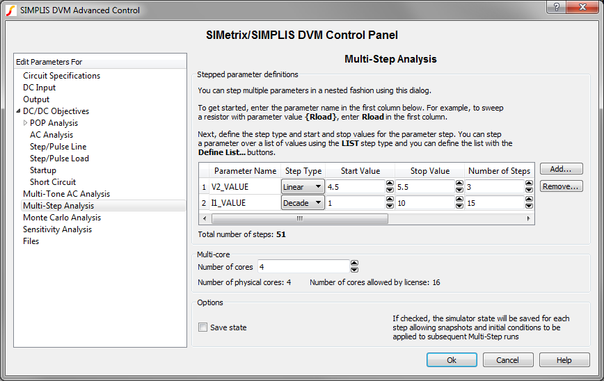 you would use a LoadComponentValues Configuration file as
below:
you would use a LoadComponentValues Configuration file as
below:| 1 | *** | ||
|---|---|---|---|
| 2 | *** | ||
| 3 | *** | ||
| 4 | DVM_CONTROL.ANALYSIS_MULTI_STEP_PARAM_NAME | V2_VALUE;I1_VALUE | |
| 5 | DVM_CONTROL.ANALYSIS_MULTI_STEP_START_VALUE | 4.5;1 | |
| 6 | DVM_CONTROL.ANALYSIS_MULTI_STEP_STOP_VALUE | 5.5;10 | |
| 7 | DVM_CONTROL.ANALYSIS_MULTI_STEP_NUM_STEPS | 3;15 | |
| 8 | DVM_CONTROL.ANALYSIS_MULTI_STEP_STEP_TYPE | LIN;DEC |
Summary of DVM Control Symbol Multi-Step Properties:
- ANALYSIS_MULTI_STEP_PARAM_NAME
- ANALYSIS_MULTI_STEP_STEP_TYPE
- ANALYSIS_MULTI_STEP_NUM_CORES
- ANALYSIS_MULTI_STEP_START_VALUE
- ANALYSIS_MULTI_STEP_STOP_VALUE
- ANALYSIS_MULTI_STEP_NUM_STEPS