PWL Transformer Model
Transformers for switching power converters are typically constructed with discrete circuit components in SIMPLIS. The saturation effects of the transformer are modeled with a PWL inductor, and the leakage inductance parasitics are typically lumped into a single leakage inductor. It is important to note that this leakage inductor must not be treated as an ideal inductor or possible slow simulation results will occur. Instead, a "Lossy Inductor" is used which has a resistor in parallel with the inductance. The resistor limits the smallest time constant present in the circuit by limiting the L/R time constant. The winding resistances are modeled with one resistor per winding.
The following example is taken from the self oscillating converter.
Example files: SelfOscillatingConverter_POP_AC_Tran.zip.
The PWL transformer model contains the following:
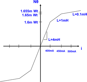
- L4: PWL Inductor for primary magnetizing inductance - includes saturation effects
- RW1: Primary winding resistance
- Lleak: Primary leakage inductance
- S1: Ideal DC Transformer (infinite magnetizing inductance)
- RW2: Secondary winding resistance
- RW3: Secondary winding resistance
L4 is based on the SIMPLIS primitive PWL inductor, which has the points defined on a X-Y plane.
An example circuit which uses this transformer can be downloaded here: SelfOscillatingConverter_POP_AC_Tran.zip
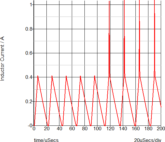
To run the simulation for this saturable inductor, follow these steps:
- Download the schematic zip file.
- Unzip and open the schematic.
- Run the simulation by pressing F9.
- Confirm the expected saturation at about 400mA.