3.0 Configuring the Schematic for DVM
DVM comes with built-in testplans, including one specifically tailored for the synchronous buck topology. The built-in DVM testplans take advantage of Full Power Assist features that require managed sources and loads.
In this section of the tutorial, you will learn how to use and configure the managed sources, managed loads, and the Full Power Assist DVM control symbol.
In order to use built-in testplans for DVM automation, your schematic must include managed DVM sources and loads and a DVM control symbol.
Managed Sources and Loads
Managed-source and managed-load symbols can represent any number of different electrical definitions, depending on the test objective of a particular simulation. While the source and load symbols do not visibly change, DVM can change the electrical definition of the subcircuit called by the symbol.
For example, DVM can change the subcircuit used by a managed-load symbol to do the following:
- Represent a simple load resistor
- Exhibit special transient behavior, such as a pulsed load to simulate a load transient
- Include an injected AC source and the Bode plot probe required for measurement in an AC Bode plot analysis
Likewise, a managed-source subcircuit has these options available:
- Represent a constant DC voltage source
- Represent a start-up ramp or a pulsed line voltage source
- Perform input impedance measurements by including components that inject an AC small signal perturbation into the circuit and measure the resulting input impedance
These are just a sample of the source and load configurations. For a complete list of available subcircuit definitions, see the Introduction to DVM.
DVM Control Symbol
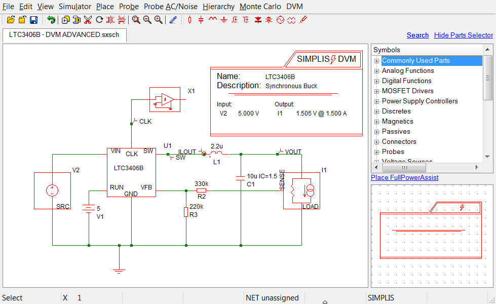
The DVM control symbol is a data-storage element containing a library of specification information about the circuit being tested. By saving the specifications for the circuit being tested to the schematic, a single testplan can be used since the specification information is stored with the schematic rather than in the testplan. The same testplan used on a 5V input, 1.5V output synchronous buck converter can be used on a 400V input, 12V output LLC converter without any modification. The DVM control symbol is, however, electrically inactive and does not contribute to the netlist.
To use DVM automation, you must have one of the two types of DVM control symbols on the schematic:
- The Basic DVM control symbol stores a limited amount of information about the
circuit:
- The circuit name and description
- The switching frequency
- The minimum phase and gain margins
- The Full Power Assist control symbol includes the same information as the basic
control, put also stores:
- The nominal, minimum, and maximum input voltage for each managed input source
- The output voltage set-point, tolerance, and maximum output current for each managed load
- Analysis information similar to the Choose Analysis dialog in SIMetrix/SIMPLIS
- Report customization information, including any pre- and post-process script names
The Full Power Assist control symbol is required when using the built-in testplans, as these testplans do not contain any specification information, such as the input voltage or output current.
All the examples in this tutorial use the Full Power Assist control symbol.
When you execute a DVM test, the program will use the analysis information included in the DVM control symbol and change the simulation parameters, which take precedence over any parameters defined from the menu option.
The steps required to add all of the above elements to a working schematic can often be completed in five minutes as explained in the following subsections: