Real Time Noise Analysis
This is an extension of transient analysis rather than a separate analysis mode. When activated, real time noise sources are added to all noisy devices with a magnitude and frequency distribution calculated using the same equations used for small signal analysis. This allows noise analysis to be performed on sampled data systems and oscillators.
To use real time noise analysis, the following parameters may be added to the .TRAN analysis line.
| RTNstep | Source step size in seconds. This will need to be small enough to cover the frequency range of interest. The noise magnitude starts rolling off at about 1/3*stepsize. Default=0 i.e. real time noise analysis disabled. |
| RTNstart | Optional. Time after analysis start at which the noise sources will be enabled. Default = zero |
| RTNstop | Optional. Time after analysis start at which the noise sources will be disabled. Default = stop time. |
In this topic:
Example
.TRAN 0 1m RTNstep=1u RTNstart=500u
Analysis time 1m, RTN step size 1u, real time sources start at 500u. The step size parameter - i.e. the first parameter on the .TRAN line - must be supplied if real time noise parameters are to be included. This is only to comply with the syntax rules not because the step size is needed for any other purpose. In most cases, just set it to zero as in the above example.
Test Results
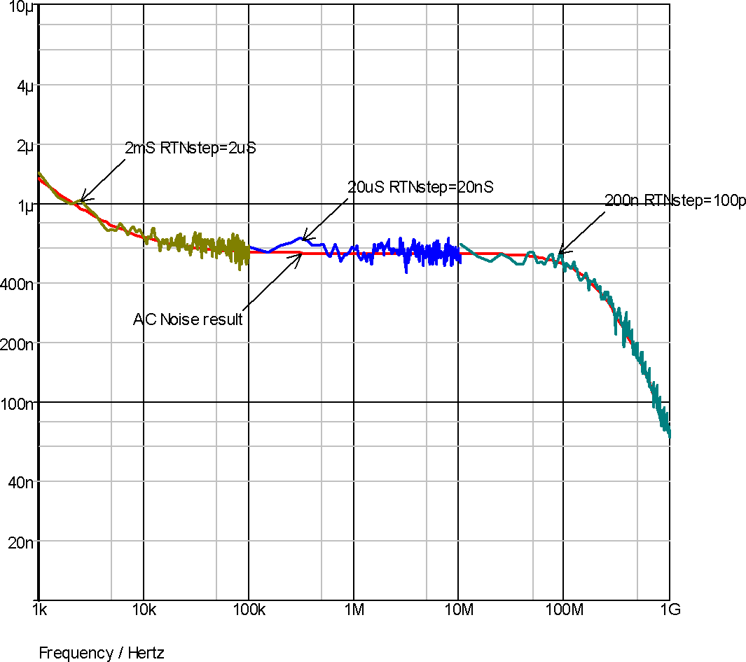
To test real time noise and verify it's accuracy we ran a test on a number of circuits which compare AC noise with real time noise. The procedure was to run real time noise analysis 50 times then plot the averaged Fourier spectrum. This test was repeated for different transient run times and step sizes to build a noise spectrum over several decades. The graph below is the result of one such test. This was carried out on the BSIM3 buffer circuit provided in one of the examples except that a value for AF - the flicker noise parameter - was added to the models. As can be seen in the graph below the real time noise results strongly follow the AC noise results.
Similar tests were performed on circuits containing each of the major noise generating devices including diodes, BJTs, JFETs, resistors (including its flicker noise parameter) and also the NXP MOS9 and MEXTRAM devices. All showed results similar to below with a close similarity between AC noise and real time noise.
These tests were performed using a simple script. This script is called rtntest.sxscr and can be found on the installation CDROM at SCRIPTS/EXAMPLES. This can also be found at our web site. Please refer to Further Documentation for details.
Real Time Noise Notes
Small-signal Noise
Traditional noise analysis operates as a small-signal mode. This analysis mode is fast and provides detailed information about noise sources. However, small-signal noise has a number of drawbacks as follows:
- Small signal noise assumes small signal linear operation about a single operating point
- Small signal noise assumes the noise itself does not disturb the operating point significantly
- Small signal noise assumes the noise can be treated as independent of the signal
- It is often difficult or impossible to determine if the small-signal assumptions are valid
As a consequence, small-signal noise is not always an appropriate analysis method. It is usually inappropriate for mixers, switched capacitor circuits and sample-holds amongst others.
Real Time Noise
Real Time Noise is real noise in the time domain. Randomly generated noise signals are applied to noisy elements in the circuit. No small signal linear assumptions are made and this mode may be used to analyse noise for any type of circuit.
Real Time Noise is implemented by connecting PWL noise sources in place of noise sources used in small signal noise analysis and using same equations to set magnitude.
For example, the shot noise in a diode is modelled by a simple current source:

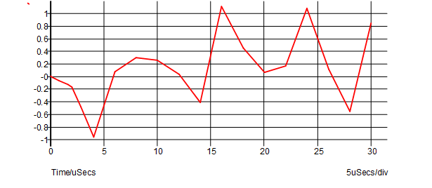
Each white noise source generates a PWL waveform where each point has a random value with a Gaussian distribution. The following picture shows a typical waveform:
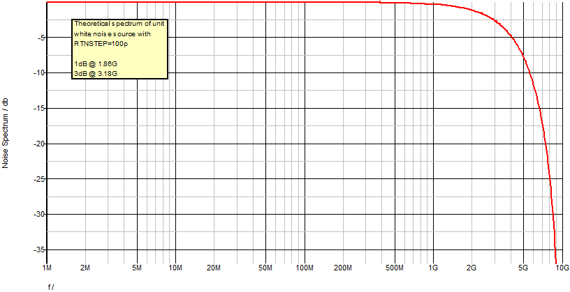
The frequency distribution of the real time noise source can be determined by this equation:
 where f is frequency and f0 = 1/rtnstep
The following plot shows the distribution for a step size of 100ps
The above describes how white noise sources are implemented. It is also necessary to implement flicker noise which has a noise distribution that varies with frequency. This is done by summing multiple PWL sources with increasing step size.
RTN Mode
Noise sources are not fixed like regular signal sources. Their amplitudes vary according to device bias conditions. But they can be treated like regular signal sources provided their amplitude is determined and fixed at the start of each real-time noise step. While simple, this method can introduce serious errors in situations where the operating point changes substantially in a time less than the noise step. This is illustrated below:
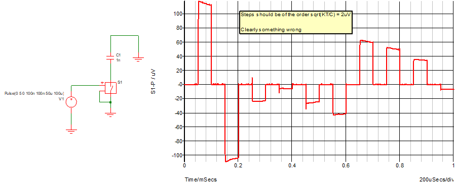
When the switch in the above circuit switches off, its conductance falls dramatically, but the noise current is set according to the on-state. This introduces gross errors as shown above.
This problem can be overcome by ensuring that the noise source is modulated on each time step not just at each noise step. If we do this, the sources can no longer be considered as fixed as they are now interfering with the device operating point. This introduces an error in the calculation of the device's partial derivative which in turn can impair convergence. However, in practice the error is small and has never been identified as a problem.
Note that devices implemented from Verilog-A code do not suffer from the problem as the SIMetrix Verilog-A compiler automatically extracts the exact derivative.
The two alternative methods described above can be selected using the RTNMODE option. RTNMODE=1 is the fixed source option whereas RTNMODE=0 is the modulated source option.
| ◄ .TRAN | Overview ▶ |