3.1 SIMPLIS Multi-Step Analysis
The ability to step or sweep parameters enables you to quickly verify a design is working as expected. In this topic, you will setup and sweep the RLoad parameter and then learn how to nest a sweep of the input voltage with the output load. In this nested multi-step simulation you will verify the converter performance over both the input voltage range and the output load range.
To download the examples for Module 3, click Module_3_Examples.zip
In this topic:
Key Concepts
This topic addresses the following key concepts:
- Design parameters can be swept with a linear or decade sweep, or over an explicit range of values.
- Multiple processor cores can be used to reduce the time required to execute a Multi-Step simulation.
- Multiple parameters can be stepped in nested sweeps by using DVM.
What You Will Learn
In this topic, you will learn the following:
- How a parameter can be stepped through a list of values, with one simulation executed per value.
- How parameters can swept over a range of values using a linear or decade sweep to determine the step size.
- How to setup and run multi-step simulations.
- How to use multiple processor cores to reduce the time required to execute a Multi-Step simulation.
Getting Started
- Close the waveform viewer if it is open.
- Open the schematic 3.1_SelfOscillatingConverter_POP.sxsch.
- From the schematic menu, select .Result: The Define SIMPLIS Multi-Step Analysis dialog opens:
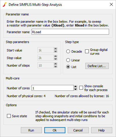
- The dialog is already prepared to step the parameter RLoad through a list of
values. To view the list of values, click on the Define List... button.Result: The Define List dialog opens, displaying the three RLoad step values: 5,2.5, and 4.2.
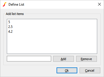
- Click Ok on the Define List dialog.
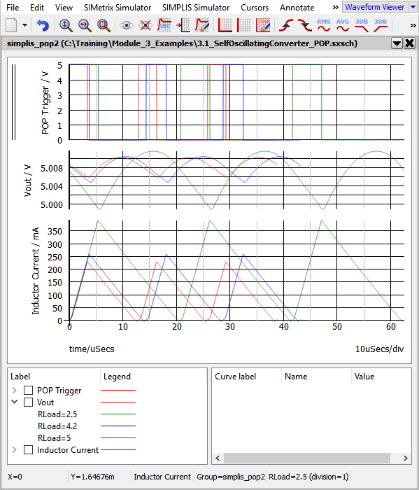
- Click Run on the Define SIMPLIS Multi-Step Analysis dialog.Result: The Multi-Step simulation runs and the periodic operating point waveforms for each RLoad value are displayed on the waveform viewer: Note that the converter switching frequency, peak inductor current, and output ripple changes for each simulated RLoad value.
Discussion
The SIMPLIS Multi-Step Analysis allows you to quickly verify how a design responds to parameter changes. In the next topic, 3.2 SIMPLIS Monte Carlo Analysis, you will learn how the SIMPLIS Monte Carlo Analysis allows you to vary multiple design parameters with statistical distributions.
In this example, three RLoad values which couldn't be defined as a linear or decade sweep were chosen. The List sweep option allows you to choose any list of values. The SIMPLIS Multi-Step Analysis allows you to sweep parameters over linear or decade steps as well. More information on the different sweep types can be found in the help topic linked to by the Help button on the Define SIMPLIS Multi-Step Analysis dialog.
How The Multi-Step Analysis Works
You may recall from the topic 3.0.1 What Happens When You Press F9? that the RLoad variable is set in the F11 window:
.var RLoad=2.5
When you ran the Multi-Step Analysis, the RLoad value defined in the F11 window was overwritten by the step value defined in the Define SIMPLIS Multi-Step Analysis dialog. For each step value, the netlist preprocessor:
- Includes the stepped parameter value, in this case RLoad.
- Pre-processes the netlist
- Launches the SIMPLIS simulator on the resulting deck.
In this example, three individual deck files were created, and each new deck file over-writes the previous deck file. This example steps the RLoad parameter over three values in the order - 5 , 2.5, 4.2. In the last deck file, R3 will have a value of 4.2Ω. In the next exercise you will verify the last value of R3 is 4.2Ω.
Exercise #1: Verify R3 Value
- From the menu bar, select .Result: The Deck file opens in the netlist editor.
- To search for the text 4.2, follow these steps:
- Use the shortcut key Ctrl+F to open the search dialog.
- Type 4.2Result: the deck file scrolls to line 110 where the value of R3 is 4.2 Ω.
109 R2 35 0 1.5 110 R3 41 0 4.2 111 R2 0 28 150
SIMPLIS Multi-Core Capability
The SIMetrix/SIMPLIS Pro and Elite licenses can use multiple processor cores to simulate the stepped parameter values.
| License | Number of Physical Cores |
| Pro | 4 |
| Elite | 16 |
In addition to the maximum number of cores allowed by your license, you are obviously limited by the number of cores your computer has. For this limitation, SIMetrix/SIMPLIS only uses the physical cores, not the hyper-threaded cores. In the next exercise you will run a multi-core, multi-step simulation.
Exercise #2: Enable Multi-Core
This exercise assumes your computer has more than one physical core and that you are using a SIMetrix/SIMPLIS Pro license.
- Close the waveform viewer.
- From the schematic menu, select .Result: The Define SIMPLIS Multi-Step Analysis dialog opens:
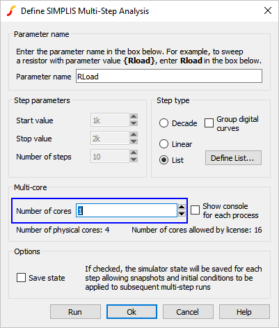
- Change the Number of cores to 4, the maximum allowed by the Pro
license. Note: If your machine has either a single core or two cores, the dialog will limit your Number of cores entry. If you have a single core, you can skip this exercise.
- Click Run.Result: The Multi-Step simulation runs on the maximum number of physical cores. Assuming you have a 4 Core machine, all 3 step values are executed simultaneously using 3 SIMPLIS processes, one per processor core. The SIMPLIS Status window has four tabs, one for each SIMPLIS process. The fourth tab is empty as no step value was run on this process:
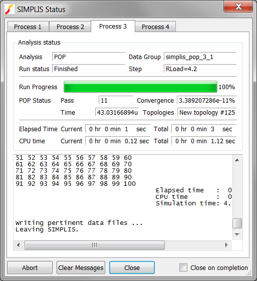
In this exercise, a very small circuit was simulated, yet you probably noticed a significant speed improvement in the time required to execute the Multi-Step Analysis. As circuit size grows, this effect becomes dramatic, and in experiments, speed improvements of approximately 3.5 times when using 4 cores vs. a single core have been found.
Using DVM to Make Nested Multi-Step Sweeps
The Design Verification Module (DVM) makes running multi-step simulations on multiple parameters very easy. In this exercise you will create and run a DVM testplan which runs a nested parameter multi-step simulation sweeping two variables, each having 3 steps.
Exercise #3: Converting A Schematic to DVM
The DVM schematic 3.2_SelfOscillatingConverter_POP_DVM_basic.sxsch is electrically identical to the schematic used in the earlier example. The only difference between this schematic and 3.1_SelfOscillatingConverter_POP.sxsch is fixed probe measurements have been added to the probes. DVM automatically makes these measurements on each parameter step and outputs the measurements to the DVM report.
To run this example circuit, follow these steps:
- Open schematic 3.2_SelfOscillatingConverter_POP_DVM_basic.sxsch.
- From the menu bar, select .Result: A DVM control symbol is necessary for any DVM simulation. A dialog asking you to place a control symbol will appear:
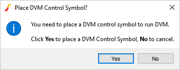
- Click Yes.Result: Focus returns to the schematic viewer with a DVM control symbol attached to your mouse.
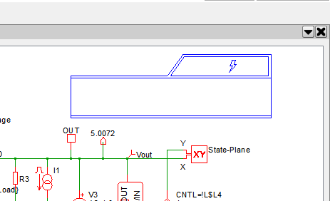
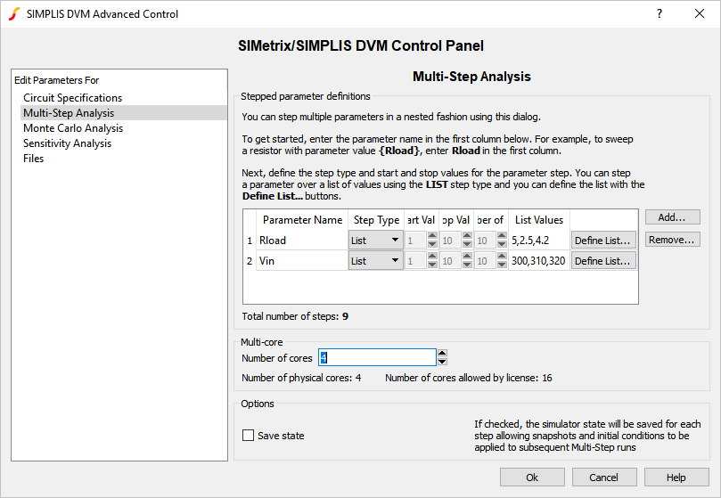
- Place the DVM control symbol on the schematic.Result: The DVM control symbol stores specification information for the schematic, including the stepped parameters. While the DVM control symbol has several forms, the one used in this example is the most basic version. The control symbol will be opened to the Multi-Step tab, where you will need to enter your multi-step parameter values:
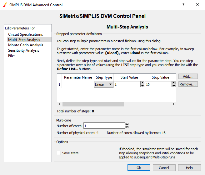
- Fill in the first parameter to match what you simulated in Exercise #2:
- Parameter Name - Rload
- Step Type - List
- List Values - 5, 2.5, 4.2
- Click Add... to add a second parameter:
- Parameter Name - Vin
- Step Type - List
- List Values - 300, 310, 320
- Increase the Number of cores to 4.Result: The control symbol Multi-Step should look like the following:
- Click Ok.Result: Probes whose names start with DVM will be output to the DVM report. Since there are none with a DVM prefix, a prompt to rename probes will appear:
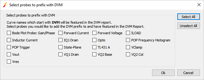
- Select the Inductor Current, POP Trigger, and Vout probes
and click Ok.Result: The selected probes will be renamed on the schematic and a description of changes made will appear on the command shell:

- Select the only test in this testplan:
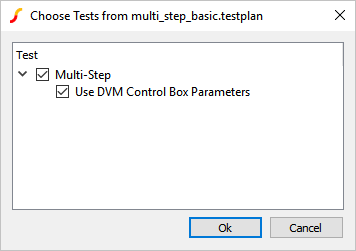
- Click Ok.Result: DVM creates the multi-step configuration file from the control symbol-defined parameters (will overwrite any existing configuration file), and outputs the following curves before opening the report.
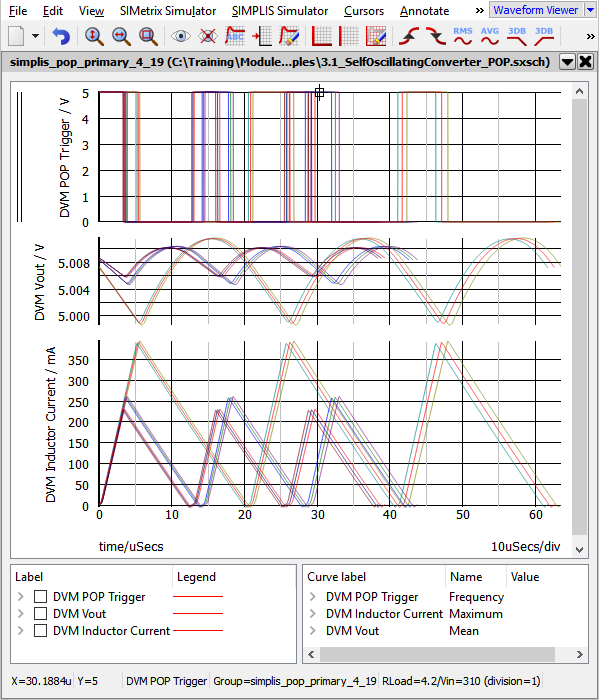
The real power of DVM lies in the HTML-formatted report generated after each test
suite runs. DVM automatically makes each probe measurement on each simulation
step, and outputs the data to the report. In the report, the stepped parameter
values and the measurements are shown in a single table: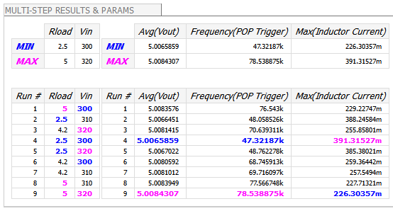
Discussion: Exercise #3
There are a few items that should be pointed out about the schematic in it's current state.
Multi-Step Configuration File
Because the Multi-Step Configuration file is created in the process described in Exercise #3, a non-DVM multi-step simulation can be conducted by clicking menu item .
DVM Testplans
DVM runs tests defined in a testplan file. Testplans are merely tab separated text files where each row represents a test to be executed, and each column performs an action during the test. To run a DVM multi-step simulation, you enter Multi-Step in the Analysis column. The Multi-Step analysis keyword tells DVM to use the parameter definitions stored on the DVM Control Symbol. In this example, the POP analysis parameters were previously defined with the menu. DVM can also change the analysis parameters on a test-by-test basis. The testplan you just ran is shown below. It has one test which runs the multi-step simulation with the parameters you defined on the DVM control symbol.
| *** | |
| *** multi_step_basic.testplan | |
| *** | |
| *?@ Analysis | Label |
| *** | |
| Multi-Step | Multi-Step|Use DVM Control Box Parameters |
| *** Documentation: http://www.simplis.com/documentation/link/simplis/6078 |
Determining The Stepped Parameter Values for a Curve
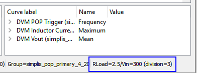
The default SIMetrix/SIMPLIS configuration has eight waveform colors. Once the number of steps exceeds 8, the colors repeat, and some curves will have the same color, making it difficult to determine which is which. To determine which curve corresponds to which stepped parameter:
- Open the waveform tab containing the multi-step waveforms.
- Hover your mouse over the target curve until you see the square box:
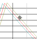
- Look at the far right side of the status bar:
Conclusions and Key Points to Remember
- The SIMPLIS Multi-Step analysis allows you to step a parameter through a list, or to sweep a parameter with linear or decade steps to evaluate the circuit performance.
- Multi-Core capability greatly reduces the time required to execute Multi-Step simulations.
- DVM allows you to quickly and easily step parameter values and collect probe measurements from each simulation step.