Example 4 -- Unregulated Converter
Shown in 9.10 is the schematic of a simple current step-up (buck) converter operating under a fixed-frequency control law. This converter is not regulated by closed-loop control and the duty ratio of the transistor Q1 is determined by comparing the fixed reference voltage of 2.5 V to the output of the triangular function generator. The SIMPLIS input file describing this converter is shown in 9.11.
Since the transistor Q1 is driven to behave like a controlled switch, it is modeled by a simple transistor switch with the LEVEL parameter set to 1. For the rest of the power stage of this converter, the diode is modeled by the piecewise-linear resistor R1 (!R$R1 in the input file), the energy -storage inductor by ideal inductance L and winding resistance RX, the output capacitor by ideal capacitor C and equivalent series resistance RC, and the load by the resistance RL.
The current through the inductor L is initialized to a value of zero at the start of the simulation to represent operation of the converter in the discontinuous-mmf mode. Waveforms obtained from this simulation are displayed in 9.12.
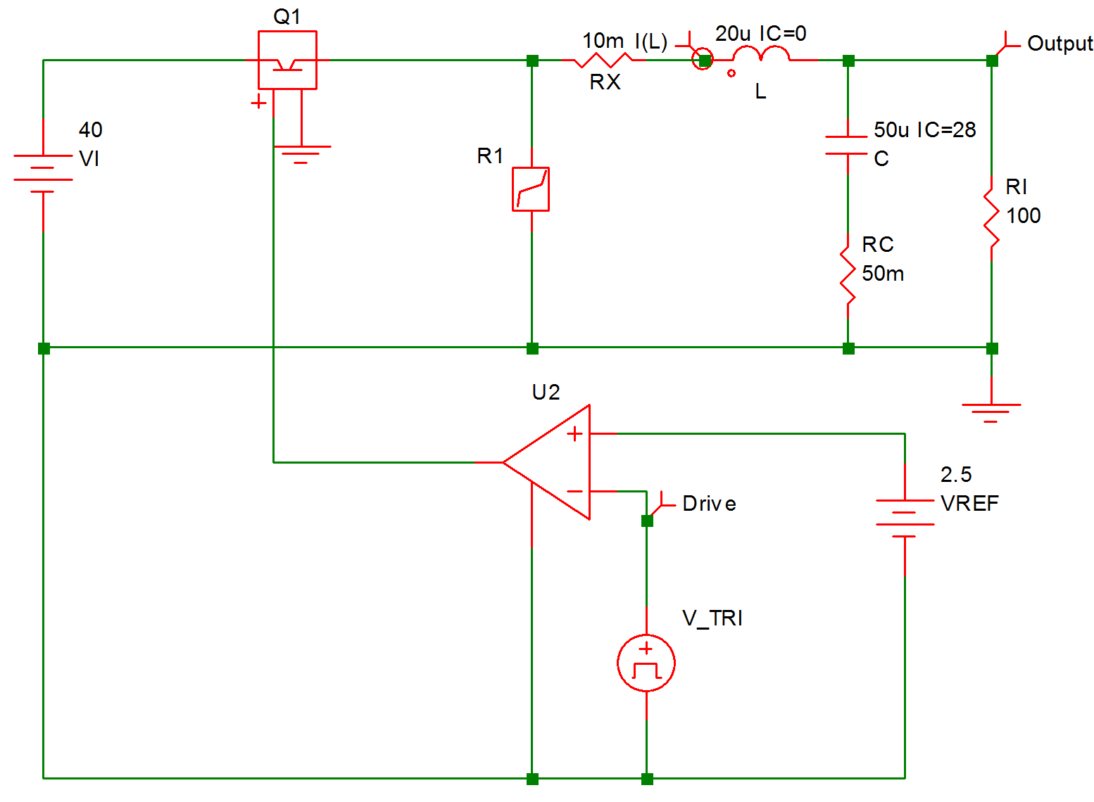 |
9.10 Unregulated Converter |
* Fixed-Frequency Unregulated Current Step-Up Converter
.PRINT  ALL
.OPTIONS  PSP_NPT=201
.TRAN 50u 0
X$U2 6 0 8 9 SIMPLIS_COMP$1
V_TRI 9 0 TRI V1=0 V2=5 FREQ=100k DRATIO=500m DELAY=0
+ OFF_UNTIL_DELAY=NO
VREF 8 0 2.5
C 5 7 50u IC=28
L 4 5 20u IC=0
VI 2 0 40
RC 7 0 50m
Rl 5 0 100
Q1 2 3 6 0 Q1$TP_VCQ IC=CLOSE
.MODEL Q1$TP_VCQ VCQPOS VSAT=700m RSAT=100m ROFF=10Meg GAIN=10
+ TH=2.5 HYSTWD=100u LOGIC=POS LEVEL=1
!R$R1 0 3 R1$TP_SSPWLR IC=1
.MODEL R1$TP_SSPWLR VPWLR NSEG=2 X0=0 Y0=0 X1=0.7 Y1=10U
+ X2=0.8 Y2=1.00001
RX 4 3 10m
.SUBCKT SIMPLIS_COMP$1  201 100 101 102
!DCOMP 201 100 101 102 MCOMP IC=1
.MODEL MCOMP COMP RIN=1e+007 ROUT=50 VOL=0 VOH=5
+ HYSTWD=1e-006 DELAY=0
.ENDS SIMPLIS_COMP$1
.END
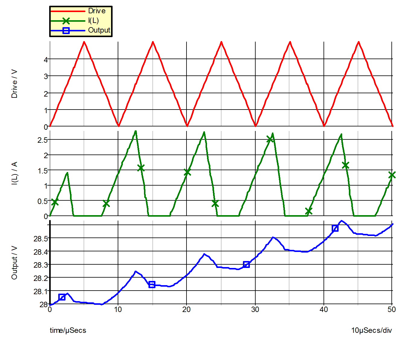 |
9.12 Waveforms for Example 4 |
| ◄ Example 3 -- Operational Amplifier with Saturation | Example 5 -- Regulated Converter ▶ |