Multi-Level Capacitor Level 0-3 w/Quantity (Version 8.0+)
The Multi-Level Capacitor has four model levels. As the level increases, additional parasitic circuit elements are added. This capacitor, available with Version 8.0 or later, is used to model a wide variety of capacitor types where the number and type of parasitic circuit elements can be configured.
In this topic:
| Model Name: | Multi-Level Capacitor (Level 0-3 w/Quantity) | |
| Simulator: |
|
This device is compatible with both the SIMetrix and SIMPLIS simulators. |
| Parts Selector Menu Location (SIMetrix): | ||
| Parts Selector Menu Location (SIMPLIS): | ||
| Symbol Library: | passives.sxslb | |
| Model File (SIMetrix): | preproc.lb | |
| Model File (SIMPLIS): | simplis_param.lb | |
| Subcircuit Name: | MULTI_LEVEL_CAP_QTY | |
| Symbol: |

|
|
| Multiple Selections: | Multiple devices can be selected and edited simultaneously. | |
Editing the Multi-Level Capacitor
To configure the Multi-Level Capacitor, follow these steps:
- Double click the symbol on the schematic to open the editing dialog to the Parameters tab.
- Choose a model level, and then make the appropriate changes to the fields described in the table below the image.
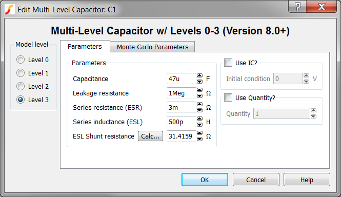
| Label | Applicable Model Levels | Units | Description |
| Capacitance | 0,1,2,3 | F | Capacitance value |
| Leakage resistance | 1,2,3 | Ω | Leakage resistance across the capacitor |
| Series resistance (ESR) | 2,3 | Ω | The equivalent series resistance (ESR) |
| Series inductance (ESL) | 3 | H | The equivalent series inductance (ESL) |
| ESL Shunt resistance | 3 | Ω | The shunt resistance in parallel with the ESL. This resistance is included to limit the maximum frequency response of the parasitic ESL, which maximizes the simulation speed in SIMPLIS mode. Click Calc... to calculate this value. |
| Use IC? | all | n/a |
|
| Initial condition | all | V | Initial voltage of the capacitor at time=0 |
| Use Quantity? | all | n/a | If checked, the model uses the specified Quantity of capacitors in parallel. |
| Quantity | all | n/a | Number of
capacitors in parallel. Note: To maximize
simulation speed when using SIMPLIS, place a single symbol and specify a
value for this parameter instead of placing multiple capacitors.
|
The model has built-in provisions for setting the Monte Carlo Parameters for all parameters except the ESL Shunt resistance. The Monte-Carlo Parameters are entered on the Monte Carlo Parameters tab shown below. To define the Monte Carlo Parameters follow these steps:
- Click on the Monte Carlo Parameters tab.
- Make the appropriate changes to the fields described in the table below the image.
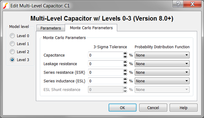
| Label | Applicable Model Levels | Units | Description |
| Capacitance | 0,1,2,3 | % | 3-sigma tolerance for the capacitance value |
| Leakage resistance | 1,2,3 | % | 3-sigma tolerance for the leakage resistance across the capacitor |
| Series resistance (ESR) | 2,3 | % | 3-sigma tolerance for the equivalent series resistance (ESR) |
| Series inductance (ESL) | 3 | % | 3-sigma tolerance for the equivalent series inductance (ESL) |
| Probability Distribution Function | all | n/a | The choices
for this function for each available parameter are the following:
|
Multi-Level Capacitor Model Levels
The Multi-Level capacitor has four levels: 0, 1, 2, and 3. As the model level increases, additional parasitic circuit elements are added to the model.
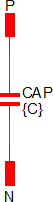
Level 0 Model
Level 0 models an ideal capacitor with no parasitic elements.
| Level 0 models these circuit elements | Level 0 Schematic | ||
|
|
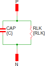
Level 1 Model
Level 1 models a capacitor with leakage resistance.
| Level 1 models these circuit elements | Level 1 Schematic | ||||
|
|
Level 2 Model
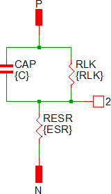
Level 2 models a capacitor with ESR and leakage resistance.
| Level 2 models these circuit elements | Level 2 Schematic | ||||||
|
|
Level 3 Model
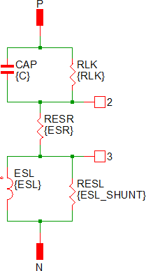
Level 3 models a capacitor with ESR, ESL, and leakage resistance.
| Level 3 models these circuit elements | Level 3 Schematic | ||||||||||
|
|
Quantity Implementation
SIMPLIS Mode
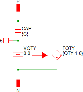
The Multi-Level Capacitor model has two quantity parameters, USE_QTY and QTY, which specify the number of capacitors in parallel. Configuring these parameters minimizes the number of reactive circuit elements in the model and, therefore, provides a maximum simulation speed.
The implementation of the quantity parameter uses a "DC Transformer" technique where the capacitor's terminal current is multiplied by a constant using a Current Controlled Current Source (CCCS). This technique effectively divides all resistance and inductance values by the quantity parameter (QTY) and multiplies the capacitance by that same value. This circuitry is added if the USE_QTY parameter is set to 1.
A schematic of the quantity implementation for a Level 0 Multi-Level Capacitor is shown below:
SIMetrix Mode
In SIMetrix, the quantity parameter is implemented with the "M" parameter which is common to the primitive SPICE components. This improves SIMetrix simulation speed and correctly scales resistances for noise analysis.
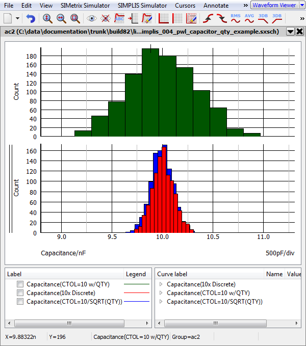
Monte Carlo Distributions With Quantity
- A single multi-level capacitor with QTY=10, and a 10% tolerance (Green histogram curve)
- 10 discrete capacitors with a 10% tolerance, wired in parallel (Red histogram curve)
- A single multi-level capacitor with a tolerance = ???MATH???\frac{\text{10%}}{\sqrt{\text{QTY}}}???MATH??? (Blue histogram curve)
Symbol Migration
Symbols placed on schematics in previous versions of SIMetrix/SIMPLIS can be automatically migrated to use the new symbols. The schematic tools menu will invoke a routine which migrates the existing symbols to the new symbols. As this action makes substantial changes to the schematic, it is recommended that you save a backup copy of the schematic first.