SystemDesigner Bus Probe (Regular Buses)
SystemDesigner uses a unique bus system which applies to every bus in the hierarchy. When the design is simulated, the program automatically determines if the design is a SystemDesigner design or a regular SIMPLIS design. A schematic design is deemed a SystemDesigner design if a single SystemDesigner component is used at any level of the hierarchy. This means you may have hierarchical schematics that have no SystemDesigner components but do have SystemDesigner buses because another schematic in the design is a SystemDesigner schematic.
Because of these different bus types, it is important to remember that the regular bus probe does not produce any curves when used on a SystemDesigner schematic. This special probe has all the functionality of the regular bus probe but produces curves only for buses on SystemDesigner schematics. Otherwise, the edit dialog, the parameters and their use are identical to the regular bus probe.
For information about the regular bus probe, see Plotting Busses.
In this topic:
| Model Name: | SystemDesigner Bus Probe (Regular Buses) | |
| Simulator: |
|
This device is compatible with the SIMPLIS simulator. |
| Parts
Selector Menu Location: |
SystemDesigner Functions (max. 32 bit) | Probes | |
| Symbol Library: | SIMPLIS_SystemDesigner_Probes.sxslb | |
| Model File: | None - Electrically inactive | |
| Subcircuit Name: | None - Electrically inactive | |
| Symbols: |
|
|
| Multiple Selections: | Only oneSystemDesigner Bus Probe (Regular Buses) may be edited at a time. | |
Editing a Regular Bus Probe
To edit the bus probe, double click on the symbol to open the probe editing dialog:
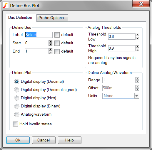
| Label | Parameter Description | ||||||
| Define Bus |
|
||||||
| Define Plot |
|
||||||
| Define Analog Waveform |
Enabled only if Analog waveform is specified in the Plot
Type box. Specifies the scaling values and units for analog
waveforms:
|
||||||
| Analog Thresholds |
Needed only if the bus contains analog signals. Defines how these signals
are converted to logic levels.
|
Examples
For examples that use the SystemDesigner Bus Probe (Regular Buses), see the following:
© 2015 simplistechnologies.com | All Rights Reserved