2.2.4 Circuits Which Cause POP to Fail
There are numerous ways a circuit will fail a POP analysis. In this topic you will learn the most common errors, and how to correct them.
To download the examples for Module 2, click Module_2_Examples.zip
In this topic:
What You Will Learn
The types of circuit issues which cause POP convergence failures include:
- Wrong parameter values for the POP Trigger device.
- POP Trigger device connected backwards.
- Multiple independent frequency sources connected to circuit elements which have state variables. These circuit elements include capacitors and inductors.
- POP Trigger connected to the wrong periodic source.
- Circuits that are unstable.
Getting Started
The common syntax errors were discussed in the previous topic, 2.2.3 POP Error Messages. In the final exercise in that topic, the correct POP Maximum period was specified and the POP analysis succeeded. Once a circuit passes the initial syntax error checker, it is still possible that the POP analysis will fail to converge during the simulation. This topic picks up with circuit errors which cause convergence failure in the SIMPLIS POP analysis. Broadly speaking, these circuit errors can be divided into three categories:
- Incorrect parameter values.
- A POP Trigger device connected to a periodic frequency which is not the least common multiple of the circuit's periodic frequencies.
- Circuits which are inherently unstable.
Discussion Part I
The first two exercises in this topic deal with parameter values inappropriate for the design, and improperly connected POP Trigger devices.
Exercise #1: Wrong POP Trigger Parameter Values
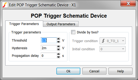
This example circuit uses the oscillator ramp for the POP trigger source; however, the ramp oscillates between 0 and 1V, while the POP Trigger threshold is set to the default value of 2.5V. Because the ramp voltage never crosses the POP Trigger threshold, the output of the POP Trigger is not switching, and the POP analysis cannot find the periodic operating point of the circuit.
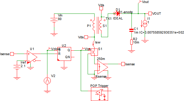
- Open the schematic 2.9_pop_fails_wrong_threshold_parameter.sxsch.
- Run the simulation. Result: The simulation runs but an error is generated because the POP Trigger output is not switching:
****************************************
<<<<<<<< Error Message ID: 5020 >>>>>>>>

Periodic Operating-Pt Analysis:

	Reaching a time duration equal to
	'4.20000e-006' without registering the
	triggering condition that defines
	the start of a period.  Check your
	circuit and/or initial conditions.
- Now, double click on the POP Trigger device. Result: The POP Trigger Schematic Device dialog opens:
- Change the Threshold parameter to 500m. The configured dialog will appear
as follows:
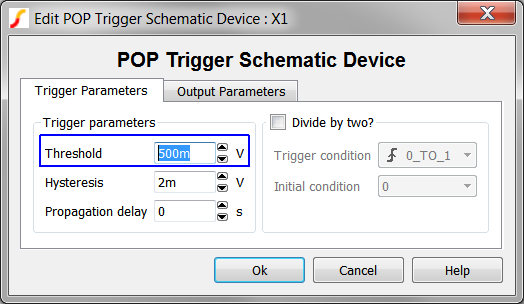
- Click the Ok button to save your changes.
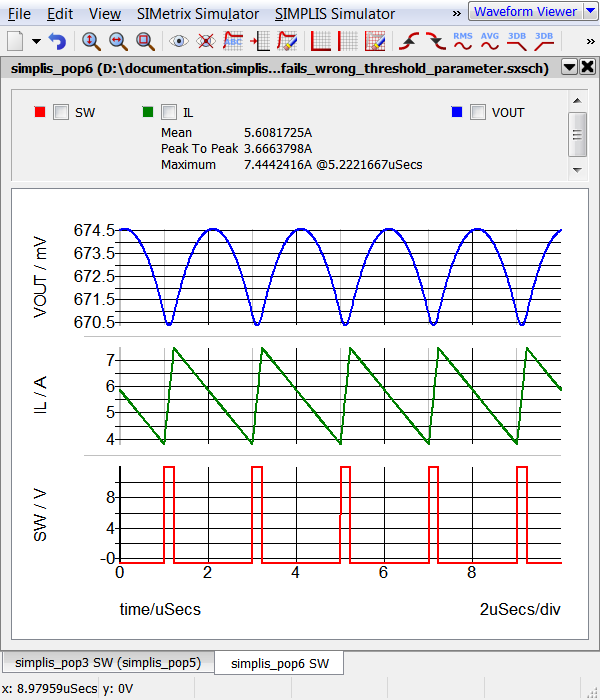
- Run the simulation. Result: The POP simulation runs and 5 cycles of the periodic waveforms appear on the waveform viewer:
Exercise #2: POP Trigger Connected Backwards
The POP Trigger schematic device has a single input and a single output. Once you are used to looking at it, one might think the input pin to the POP Trigger device is obvious, but SIMPLIS does receive occasional tech support requests from new users where the output of the POP Trigger is connected to the periodic waveform.
To run this exercise, follow these steps:
- Open the schematic 2.10_pop_fails_backwards_pop_trigger.sxsch.
- Run the simulation. Result: The simulation runs but an error is generated because although the circuit is switching, the actual POP Trigger output is not switching because the input to the POP Trigger is floating:
****************************************
<<<<<<<< Error Message ID: 5020 >>>>>>>>

Periodic Operating-Pt Analysis:

	Reaching a time duration equal to
	'4.00000e-005' without registering the
	triggering condition that defines
	the start of a period.  Check your
	circuit and/or initial conditions.
- If you reconnect the POP Trigger device so the input is connected to the periodic frequency signal, the circuit will converge in a POP analysis. This is left as an exercise for the user.
Discussion Part II
The final three exercises deal with the heart of the POP analysis. These exercise demonstrate the other circuit conditions where POP can fail, including multiple non-synchronous frequencies, and circuits which are inherently unstable.
Exercise #3: Multiple Asynchronous Frequencies
The first exercise uses the schematic: 2.11_pop_fails_different_frequencies.sxsch, which has three asynchronous frequency sources. The frequencies are:
- 1MegHz
- 600kHz
- 200kHz
Both the 1MegHz and 600kHz sources drive resistor-capacitor networks, and these capacitor voltages are sampled during the Core POP Process. Because the capacitors are driven at two different frequencies which are not harmonically related, the POP analysis will fail. This exercise will help you to better understand the how the SIMPLIS POP analysis can successfully analyze circuits with multiple asynchronous frequencies. To get started,
- Open the schematic 2.11_pop_fails_different_frequencies.sxsch.
- Run the simulation. Result:
- The simulation runs but the POP analysis doesn't converge.
- The SIMetrix/SIMPLIS Command Shell displays the
error message, which indicates C2, the capacitor connected to the 1MegHz
source is the main cause of the POP failure.
**************************************** <<<<<<<< Error Message ID: 5019 >>>>>>>> Periodic Operating-Pt Analysis: Unable to find a periodic operating point after 20 attempts. Check your input file for errors. A change in the initial condition may be necessary. The voltages of the following capacitors and the currents of the following inductors are the leading contributing factors to the non-convergence of the POP analysis. Inspecting these voltages/currents from the "POP progress output" may show the clues to the non-convergence. C2 - SIMPLIS proceeds with a transient simulation for 4us. This time was intentionally set in the POP Advanced options.
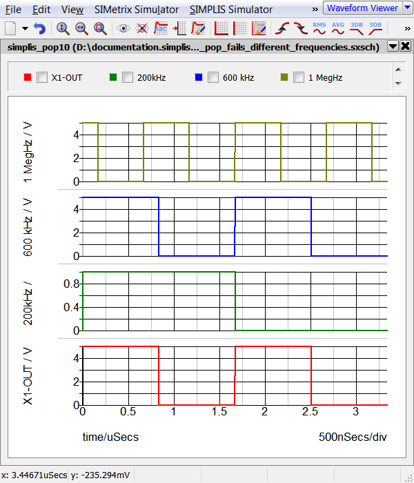
- The output waveforms are displayed on the waveform
viewer:
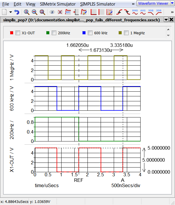
Examining the graph output, notice how on the POP Trigger rising edges, the 1MegHz signal has two different values from one POP Trigger edge to the next. Since the 1MegHz signal drives a reactive component, C2, the sampled change in C2 voltage from one trigger edge to the next is 5V, and POP analysis fails to converge.
In the next two mini-exercises, you will learn that:
- The circuit is periodically stable at the lowest common multiple of the independent frequency sources. In this circuit, this is 200kHz.
- The multiple, independent frequencies only effect POP if the frequency sources drive reactive components.
Exercise #3a: Change Periodic Source
In this mini-exercise, you will change the POP Trigger source to use the 200kHz signal generated by the divide_freq_by_three.sxcmp schematic component. Because 200kHz is the least common multiple of 1MegHz and 600kHz, the circuit is periodically stable at 200kHz and the POP simulation will converge.
- Double click on the jumper J1 to open the editing dialog. Result: the Edit Jumper Parameters: J1 dialog opens:
- Click on the Position 1 radio button. The configured dialog should appear
as follows:
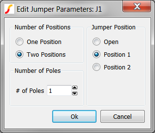
- Click Ok. Result: The jumper symbol changes, showing the jumper has moved to the first position, which connects the 200kHz signal to the POP Trigger.
- Run the simulation. Result: The circuit converges to steady-state in the SIMPLIS POP analysis. The waveform viewer displays two cycles of the 200kHz POP Trigger signal:
Notice the time instants where the cursors are placed in the above graph. At every POP trigger edge, the 600kHz signal is always at 5V, and 1 Meg Hz signal is also at 5V. POP succeeds because the capacitor voltages are the same from one POP Trigger edge to the next.
Another interesting fact can be learned by eliminating the capacitor C2 and triggering on the 600kHz signal. The next mini-exercise will demonstrate this.
Exercise #3b: Remove C2
In this mini-exercise, you will remove C2 from the circuit and change the POP Trigger to use the 600kHz signal. You will see that although the waveforms are identical to the simulation you ran in the Getting Started section, simulation will converge.
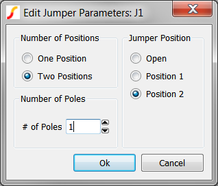
- Delete C2 from the schematic.
- Edit the Jumper J1, changing it's position to Position 2. This will connect the 600kHz signal to the POP Trigger.
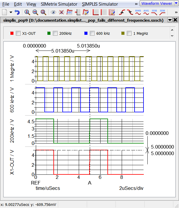
- Run the simulation. Result: The circuit converges to steady-state in the SIMPLIS POP analysis. The waveform viewer displays the periodic results:
Although the circuit has three asynchronous frequencies, only one, the 600kHz signal is connected to a reactive component. Because the POP Trigger is connected to the 600kHz signal, the POP analysis succeeds.
Exercise #4: Wrong Periodic Signal - LLC Converter
In exercise #3, you learned that a circuit can be periodically stable at the lowest common multiple the independent frequencies present in the circuit. Although the example circuit used was overly simplified, this concept is also important for bridge-type and multi-phase converters. In this example you will see how to apply this concept to a LLC half-bridge converter.
- Open the schematic 2.12_pop_fails_wrong_periodic_signal.sxsch.
- Run the simulation. Result:
- The simulation runs but the POP analysis doesn't converge.
- SIMPLIS produces the following error message box:
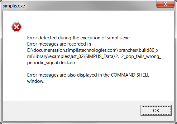
- Click OK. Result: The error messages are output to the SIMetrix/SIMPLIS Command Shell:
****************************************
<<<<<<<< Error Message ID: 5020 >>>>>>>>

Periodic Operating-Pt Analysis:

	Reaching a time duration equal to
	'3.00000e-005' without registering the
	triggering condition that defines
	the start of a period.  Check your
	circuit and/or initial conditions.
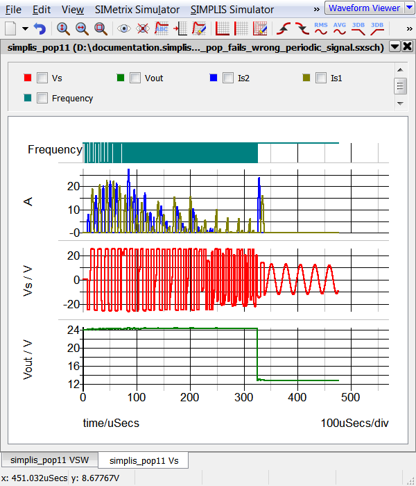
In this example, the oscillator frequency, which is twice the frequency of the individual bridge MOSFETs, is used for the POP Trigger. The circuit is not periodic at the oscillator frequency, and the Core POP Process fails to find a periodic operating point. The transfer function of the LLC converter is quite complex, and, with the wrong initial conditions, the converter ceases to switch altogether. This happens in this example circuit, and the POP error message as well as the "Output POP Progress" waveforms show this:
There are two ways to select the appropriate frequency for the POP Trigger source:
- Use the "Divide by Two" feature of the POP Trigger gate.
- Select one of the primary side gate drive waveforms as the POP Trigger source.
The next two mini-exercises demonstrate these methods.
Exercise #4a: Use the Divide By Two Feature of the POP Trigger
In this mini-exercise, you will configure the POP Trigger schematic device to divide the incoming frequency by two and use this signal as the POP Trigger.
- Double click on the POP Trigger device to open the editing dialog.
- Select the Divide By Two check box. The configured dialog will appear as
follows:
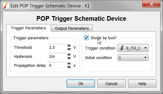
- Click Ok to save your changes.
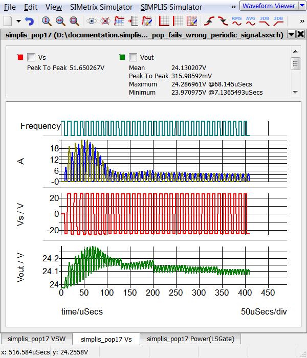
- Run the Simulation. Result: The simulation converges in the POP analysis and because the Output POP Progress option is set, the entire progress of the simulation up until steady-state is reached is displayed on the waveform viewer: Note- in the graph shown below, the Vs tab has been selected, while the waveform viewer will, by default, open to the last tab.
Exercise #4b: Select Lowest Common Frequency
In this mini-exercise, you will change the jumper J1 to select the already divided by two signal from the LLC Modulator schematic component.
- Double click on the POP Trigger device to open the editing dialog.
- Un-check the Divide By Two check box.
- Click the Ok button to save your changes.
- Double click on the jumper symbol J1.
- Select Position 1.
- Click the Ok button to save your changes.
- Run the Simulation. Result: The simulation converges in the POP analysis as in exercise 4a.
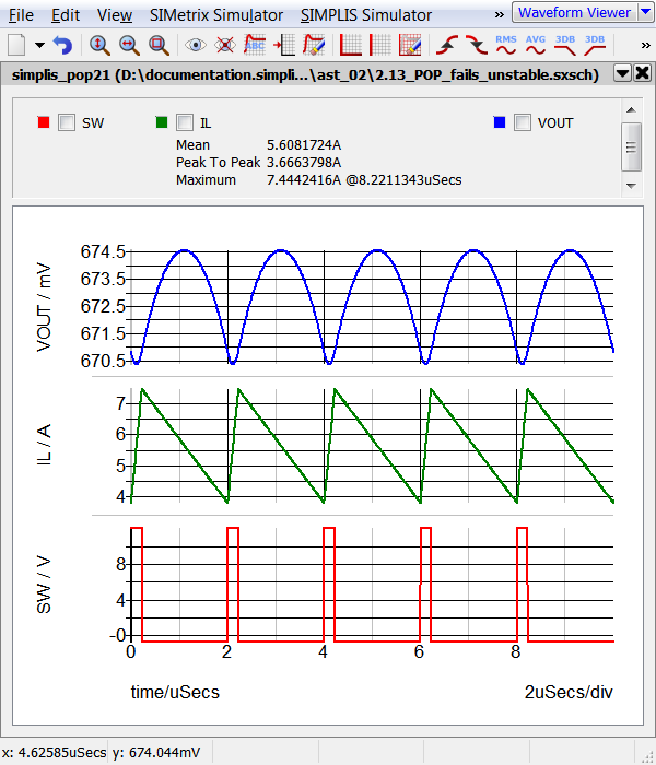
Exercise #5: Inherently Unstable Circuits
Circuits which are inherently unstable will fail to converge in a POP analysis. In the example circuit for this exercise a "noise" source has purposely been included , V5, which makes the converter appear to be unstable. By "unstable", we mean the circuit state variables do not have the same values at any given point in every switching cycle. This extremely well controlled test case is useful to study how the Core POP Process "thinks" of circuit stability.
- Open the schematic 2.13_pop_fails_different_frequencies.sxsch.
- Run the simulation. Result:
- The simulation runs but the POP analysis doesn't converge.
- An error message is output to the SIMetrix/SIMPLIS
command shell stating that the periodic operating point wasn't found
after 20 attempts. The two state variables which have the highest error
are the main power inductor and the output capacitor.
****************************************
<<<<<<<< Error Message ID: 5019 >>>>>>>>

Periodic Operating-Pt Analysis:

	Unable to find a periodic operating
	point after 20 attempts.  Check your
	input file for errors.  A change in
	the initial condition may be necessary.

The voltages of the following capacitors and the
currents of the following inductors are the leading
contributing factors to the non-convergence of the
POP analysis.  Inspecting these voltages/currents
from the "POP progress output" may show the clues to
the non-convergence.

	L1,  X$C1.C1
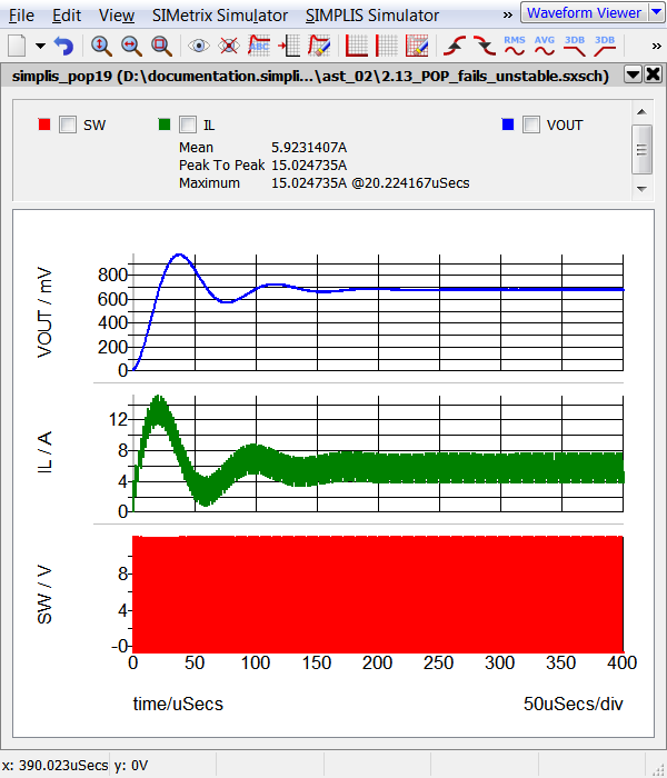
- The simulation runs the transient simulation to the
stop time defined in the POP Advanced Options, which is 400us.
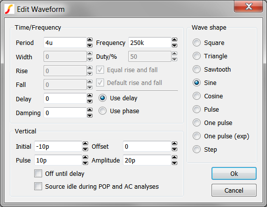
The noise source V5 in this example has a very small amplitude of only 10pV, and has a frequency of 250kHz, which is half the converter switching frequency. Although this magnitude is extremely small, it is still large enough for the Core POP Process to fail to converge to a solution. This demonstrates that POP doesn't think of circuits as "close to steady-state," instead, POP looks for a very accurate solution before declaring the circuit to be in steady-state.
Next, consider the SIMPLIS Status Window. The messages show that POP was extremely close to converging, but failed:
	PERIODIC OPERATING-POINT ANALYSIS


                                   New topology #6
                                   New topology #7
                                   New topology #8
                                   New topology #9
                                   New topology #10
                                   New topology #11
                                   New topology #12
	PASS   1: 4.523460e+000 %
	PASS   2: 1.349262e-002 %
	PASS   3: 3.480535e-007 %
	          1.477231e-009 %
	          1.627381e-009 %
	PASS   4: 1.626863e-009 %
	PASS   5: 1.155417e-010 %
	PASS   6: 1.188566e-010 %
	          1.984841e-009 %
	PASS   7: 1.887082e-009 %
	PASS   8: 1.250316e-010 %
	PASS   9: 1.261864e-010 %
	          2.113646e-009 %
	PASS  10: 1.977947e-009 %
	PASS  11: 1.282831e-010 %
	PASS  12: 1.286723e-010 %
	          2.156041e-009 %
	PASS  13: 2.007530e-009 %
	PASS  14: 1.293827e-010 %
	PASS  15: 1.294782e-010 %
	          2.169713e-009 %
	PASS  16: 2.017059e-009 %
	PASS  17: 1.296934e-010 %
	PASS  18: 1.297330e-010 %
	          2.173975e-009 %
	PASS  19: 2.020007e-009 %
	PASS  20: 1.298325e-010 %
                                   Elapsed time   :  0 hr  0 min  1    sec
                                   CPU time       :  0 hr  0 min  0.01 sec
                                   Simulation time: 0.000000000000e+000 sec
An interesting conclusion can be drawn from this exercise. If the error signal is small enough, the POP analysis should converge, even though the circuit is actually operating with a small perturbation.
Exercise #5a: Reduce Error Signal Amplitude
In this example you will reduce the error signal amplitude by an order of magnitude.
- Double click on the waveform generator V5 to open the Edit Waveform
dialog. Result: the Edit Waveform dialog opens:
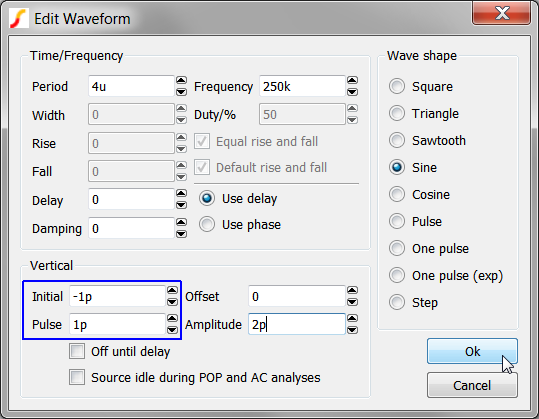
- Change the Initial value to -1p and the Pulse value to 1p. The
edited dialog should appear as follows:
- Click Ok to save your changes.
- Close the waveform viewer.
- Run the simulation. Result: The POP analysis converges. Five cycles of periodic output are generated. Although the curves appear to be in steady state, the converter is actually operating with the very small perturbation generated by the noise source V5.
Further Study
The frequency of the noise source V5 was purposely set to exactly 250kHz, which is half the converter switching frequency. Therefore, using the POP Trigger "Divide By Two" option will cause the circuit to converge in a POP analysis. This is true no matter the signal amplitude of the noise source V5. Try it!
Author's comment: This behavior is no different than the circuit converging on a sub-harmonic oscillation. In the provided example circuit, the maximum POP period was purposely set to allow the POP analysis to converge on a 4us period. You really should avoid this, and set the maximum POP Period to 110% of your expected maximum period. This prevents unintended POP convergence on sub-harmonic oscillations.
Conclusions and Key Points to Remember
There are many types of circuits which will cause POP convergence failures Including:
- Wrong parameter values for the POP Trigger device.
- POP Trigger device connected backwards.
- Multiple independent frequency sources connected to state variables.
- POP Trigger connected to the wrong periodic source.
- Circuits that are unstable.
Module Evaluation Form
Please fill out the Module # 2 Evaluation form.