Parameterized Opto Coupler (Version 8.0+)
The Parameterized Opto Coupler models a opto coupler with a one or two pole frequency response, output transistor saturation characteristics, and photo diode forward voltage drop characteristics.
In this topic:
| Model Name: | Parameterized Opto Coupler (Version 8.0+) | |
| Simulator: | This device is compatible with the SIMPLIS simulator | |
| Parts Selector Menu Location: | Analog Functions | Parameterized Opto Coupler (Version 8.0+) | |
| Symbol Library: | simplis_analog_functions.sxslb | |
| Model File: | simplis_analog_functions.lb | |
| Symbol Name: | SIMPLIS_PARAM_OPTO | |
| Subcircuit Name: | SIMPLIS_PARAM_OPTO | |
| Symbol: | 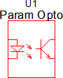
|
|
| Multiple Selections: | Multiple devices can be selected and edited simultaneously. | |
Previous Version Compatibility
This symbol and the electrical model was introduced with version 8.0 and will not simulate in releases prior to Version 8.0.
For a opto coupler version compatible with versions prior to version 7.20, download the schematic component simplis_074_opto_for_versions_prior_to_8p0.sxcmp. Although not identical to this model, the optocoupler schematic component incorporates many of the features of this model.
Symbol Migration
Symbols placed on schematics in previous versions of SIMetrix/SIMPLIS can be automatically migrated to use the new symbols. The schematic tools menu will invoke a routine which migrates the existing symbols to the new symbols. As this action makes substantial changes to the schematic, it is recommended that you save a backup copy of the schematic first.
Editing the Parameterized Opto Coupler
To configure the Parameterized Opto Coupler, follow these steps:
- Double click the symbol on the schematic to open the editing dialog.
- Make the appropriate changes to the fields described in the table below the image.
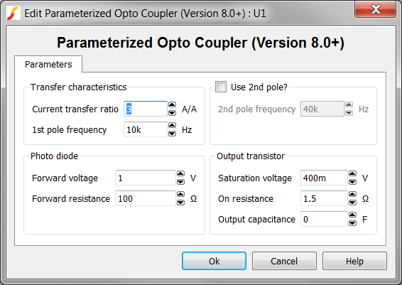
| Parameter Label | Units | Description |
| Current transfer ratio | A/A | The current transfer ratio of the opto coupler. |
| 1st pole frequency | Hz | The opto
coupler model allows you to define two poles in the transfer function. This is the first pole frequency. You can set this to 0 to remove the pole from the model. |
| Use 2nd pole? | Inserts a second pole into the model | |
| 2nd pole frequency | Hz | The opto
coupler model allow you to define two poles in the transfer function. This is the second pole frequency and is only used if the Use 2nd pole? checkbox is selected. |
| Forward voltage | V | The photo diode forward voltage. |
| Forward resistance | Ω | The photo
diode forward resistance in Ohms. The diode is modeled with a two-segment PWL resistor this is the resistance of the conducting segment. |
| Saturation voltage | V | The output transistor saturation voltage. |
| On resistance | Ω | The on resistance of the opto coupler output transistor. |
| Output capacitance | F | The
collector to emitter capacitance of the opto coupler output transistor. Set to 0 to remove the capacitor from the circuit. |
Example - DC Transfer Characteristics
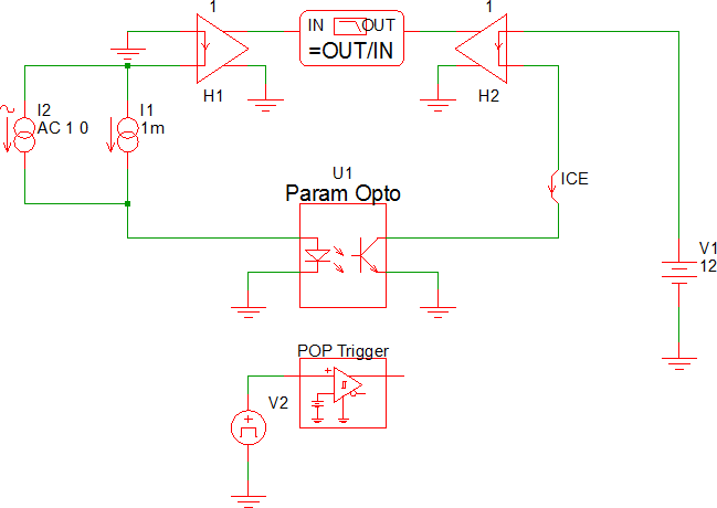
The DC transfer characteristics can be verified with this test circuit : simplis_074_opto_dc_transfer.sxsch .
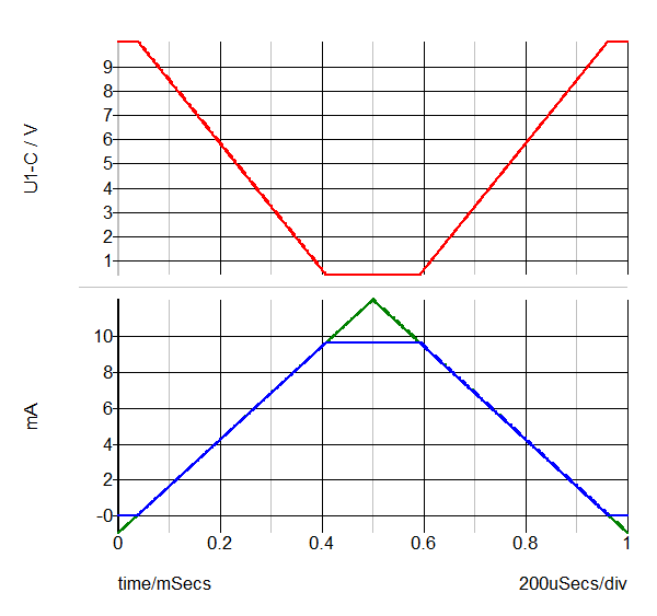
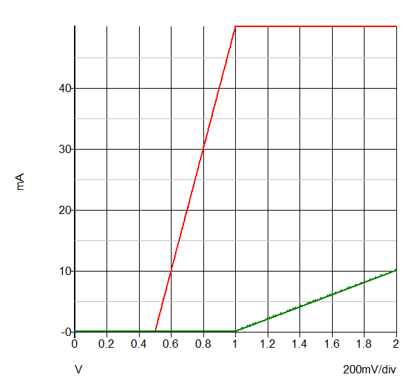
Waveforms - Transfer Characteristics
- The waveforms shown below are for a test circuit with the following opto coupler
parameters:
- Current transfer ratio of 1 V/V (0dB)
- Transistor saturation voltage of 400mV
Waveforms - Saturation Characteristics
The waveforms shown below are for a test circuit with the following opto coupler parameters:
- Diode forward resistance of 100mΩ
- Transistor saturation voltage of 500mV
- Diode forward resistance of 10Ω
Example - Frequency Response
The test circuit used to generate the waveform examples in the next section can be downloaded here: simplis_074_opto_single_pole_freq_response.sxsch.
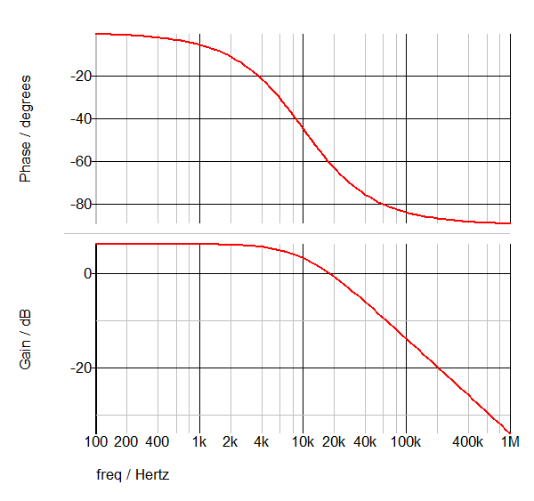
Waveforms - Single Pole
The waveforms shown below are for a test circuit with the following opto coupler parameters:
- Single pole
- 10kHz pole frequency
- Current transfer ratio of 2 V/V (6dB)
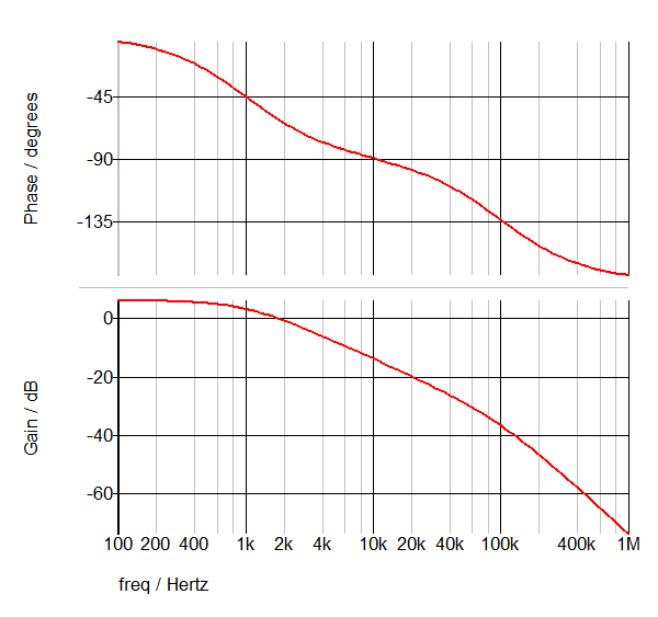
Waveforms - Two Poles
The waveforms shown below are for a test circuit with the following opto coupler parameters:
- Two poles
- 1kHz and 100kHz pole frequencies
- Current transfer ratio of 2 V/V (6dB)