POP Trigger Schematic Device
The SIMPLIS Periodic Operating Point (POP) analysis requires the user to designate a switching node which is the least common multiple of the periodic frequencies present in the circuit. For a circuit with a single operating frequency, such as a Synchronous Buck converter, the oscillator or the power stage switching node defines the periodic frequency. For a bridge converter where two switches are operating at one-half the oscillator frequency, either of the bridge switches is a suitable periodic switching frequency. The POP Trigger Schematic Device allows a convenient way to define the trigger gate for a POP analysis without having to define the gate using low-level syntax.
In this topic:
| Model Name: | POP Trigger Schematic Device | |
| Simulator: | This device is compatible with the SIMPLIS simulator | |
| Parts Selector Menu Location: | ||
| Symbol Library: | simplis_analog_functions.sxslb | |
| Model File: | simplis_param.lb | |
| Symbol Name: | PERIODIC_OP_V8 | |
| Subcircuit Name: | PERIODIC_OP | |
| Symbol: | 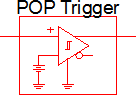
|
|
| Multiple Selections: | Only one POP Trigger device is permitted on a schematic. | |
Previous Version Compatibility
This symbol was introduced with version 8.0; however, the model and supporting files are available in version 7.20 as well. In versions prior to 7.20, the schematic will simulate, but you will not be able to edit the parameters with the dialog pictured in this topic.
For a version of the POP Trigger Schematic Device compatible with versions prior to version 7.20, see the parts selector entry:
Symbol Migration
Symbols placed on schematics in previous versions of SIMetrix/SIMPLIS can be automatically migrated to use the new symbols. The schematic tools menu will invoke a routine which migrates the existing symbols to the new symbols. As this action makes substantial changes to the schematic, it is recommended that you save a backup copy of the schematic first.
Editing the POP Trigger Schematic Device
The default parameter values for the POP Trigger Schematic Device are appropriate for most circuits. If you are experiencing simulator errors, the most likely cause is the POP analysis directives are not appropriate for your circuit. For more information, see the following topics:
- SIMPLIS Tutorial: 3.2 Set up a POP Analysis
- Advanced SIMPLIS Training : 2.3.1 Overview of the Periodic Operating Point (POP) Analysis
- Advanced SIMPLIS Training : 2.3.3 POP Syntax Errors
To configure the POP Trigger Schematic Device, follow these steps:
- Double click the symbol on the schematic to open the editing dialog.
- Make the appropriate changes to the fields described in the table below the image.
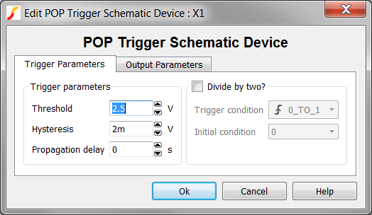
| Parameter Label | Units | Description | |||||||
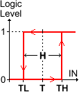
| Threshold Hysteresis |
V |
|
The
Threshold (T) and Hysteresis (H) of the POP
Trigger Schematic Device. To determine the low-to-high threshold (TH)
and the high-to-low threshold (TL), substitute Threshold
(T) and Hysteresis (H) in each of the following
formulas :
|
||||||
| Propagation delay | s | The propagation delay of the POP Trigger Schematic Device. | |||||||
| Divide by two? | Inserts a toggle flip-flop into the POP Trigger Schematic Device model. Primarily used for bridge converters, this allows you to use the master clock as the POP trigger source, the toggle flip-flop will produce a divided by two signal for the actual POP trigger gate used by SIMPLIS. | ||||||||
| Trigger condition | Determines the triggering
condition of the input pin:
|
||||||||
| Initial condition | The initial condition of the output when Divide by two? is checked. | ||||||||
To edit the output Parameters, click on the Other Parameters tab. The parameters simply set the output levels for the POP Trigger Schematic Device. Changing these parameters will not help you circuit converge in a POP analysis, nor will changing these parameters affect the POP errors.
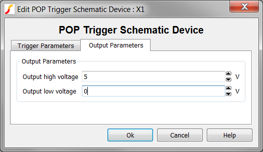
| Parameter Label | Units | Description |
| Output high voltage | V | The high voltage of the output pin. |
| Output low voltage | V | The low voltage of the output pin. |