Multi-Level PWL Capacitor w/ Level 0-3 (Version 8.0+)
The Multi-Level PWL Capacitor model has the same model levels as the Multi-Level Capacitor, and other than the internal capacitor, the models are identical. The capacitor internal to the PWL capacitor can have up to 10 segments and the capacitance is defined on a Charge vs. Voltage plane. As the model level increases, so does the model complexity. This capacitor is available with Version 8.0 or later.
In this topic:
| Model Name: | Multi-Level PWL Capacitor (Level 0-3 w/Quantity) | |
| Simulator: |
|
This device is compatible with the SIMPLIS simulator. |
| Parts Selector Menu Location: | ||
| Symbol Library: | passives.lb | |
| Model File: | simplis_param.lb | |
| Subcircuit Name: | MULTI_LEVEL_PWL_CAP_QTY | |
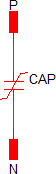
| Symbol: |

|
|
| Multiple Selections: | Multiple devices can be selected and edited simultaneously. | |
Editing the Multi-Level PWL Capacitor
To configure the Multi-Level PWL Capacitor, follow these steps:
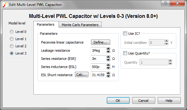
- Double click the symbol on the schematic to open the editing dialog to the Parameters tab.
- Choose a model level, and then make the appropriate changes to the fields described in the table below the image.
| Label | Applicable Model(s) | Units | Description |
| Piecewise linear capacitance | 0,1,2,3 | F |
Capacitance parameters. SIMPLIS uses Piecewise linear (PWL) modeling techniques to model non-linear devices, which are defined using a table of X, Y points. Click Define... to open the table editor to define the Voltage and Charge points. To insert rows in the table, select the number of rows you want to insert and press the insert key. To delete rows, select those you want to delete and press the delete key. |
| Leakage resistance | 1,2,3 | Ω | Leakage resistance across the capacitor |
| Series resistance (ESR) | 2,3 | Ω | The equivalent series resistance (ESR) |
| Series inductance (ESL) | 3 | H | The equivalent series inductance (ESL) |
| ESL Shunt resistance | 3 | Ω | The shunt
resistance in parallel with the ESL. This resistance is included to limit
the maximum frequency response of the parasitic ESL, which maximizes the
simulation speed. Click Calc... to calculate this value. |
| Use IC? | 0,1,2,3 | n/a |
|
| Initial condition | 0,1,2,3 | V | Initial voltage of the capacitor at time=0 |
| Use Quantity? | 0,1,2,3 | n/a | If checked, the model uses the specified Quantity of capacitors in parallel. |
| Quantity | 0,1,2,3 | n/a | Number of
capacitors in parallel. Note: To maximize
simulation speed when using SIMPLIS, place a single symbol and specify a
value for this parameter instead of placing multiple capacitors.
|
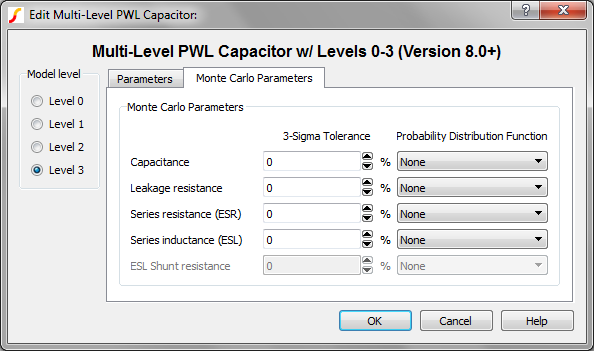
The Monte Carlo Parameters are shown and explained below.
| Label | Applicable Model(s) | Units | Description |
| Capacitance | 0,1,2,3 | % | 3-sigma tolerance for the capacitance value |
| Leakage resistance | 1,2,3 | % | 3-sigma tolerance for the leakage resistance across the capacitor |
| Series resistance (ESR) | 2,3 | % | 3-sigma tolerance for the equivalent series resistance (ESR) |
| Series inductance (ESL) | 3 | % | The equivalent series inductance (ESL) |
| Probability Distribution Function | n/a | n/a | The choices
for this function for each available parameter are the following:
|
Multi-Level PWL Capacitor Model Levels
The Multi-Level PWL capacitor has four levels: 0, 1, 2, and 3. As the model level increases, so does the model complexity; and, as a rule, simulation times also increase.
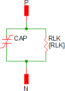
Level 0 Model
Level 0 models an ideal capacitor with no parasitic elements.
| Level 0 models these circuit elements | Level 0 Schematic | ||
|
|
Level 1 Model
Level 1 models a capacitor with leakage resistance.
| Level 1 models these circuit elements | Level 1 Schematic | ||||
|
|
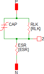
Level 2 Model
Level 2 models a capacitor with ESR and leakage resistance.
| Level 2 models these circuit elements | Level 2 Schematic | ||||||
|
|
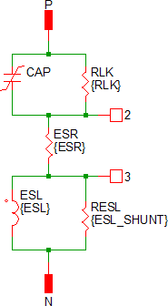
Level 3 Model
Level 3 models a capacitor with ESR, ESL, and leakage resistance.
| Level 3 models these circuit elements | Level 3 Schematic | ||||||||||
|
|
Quantity Implementation
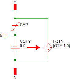
The Multi-Level PWL Capacitor model has two quantity parameters, USE_QTY and QTY, which specify the number of capacitors in parallel. Configuring these parameters minimizes the number of reactive circuit elements in the model and, therefore, provides a maximum simulation speed.
The implementation of the quantity parameter uses a "DC Transformer" technique where the capacitor's terminal current is multiplied by a constant using a Current Controlled Current Source (CCCS). This technique effectively divides all resistance and inductance values by the quantity parameter (QTY) and multiplies the capacitance by that same value. This circuitry is added if the USE_QTY parameter is set to 1.
A schematic of the quantity implementation for a Level 0 Multi-Level PWL Capacitor is shown below:
Example
An example schematic can be downloaded here: simplis_007_multi_level_pwl_capacitor_example.sxsch.
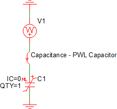
Shown below is a four segment capacitor taken from a data sheet curve of a 47uF, 1206 MLCC capacitor, these are the default parameters for the symbol:
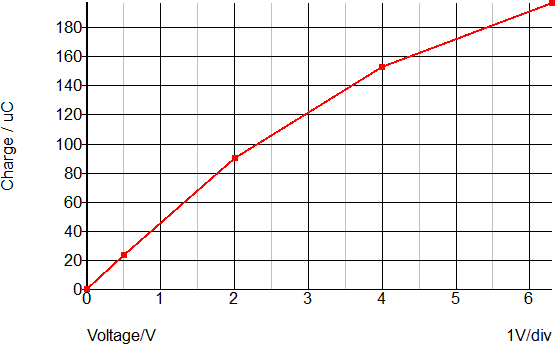
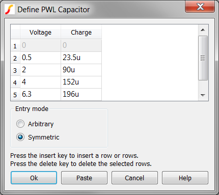
These Voltage-Charge point pairs are input on a PWL table dialog, which is opened by clicking on the "Define..." button:
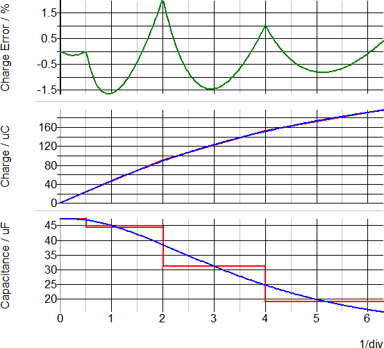
Waveforms
This schematic has the datasheet curve points stored in a script located in the schematic's F11 window. After pressing F9 to run the schematic, the data sheet curves for the capacitance and charge are automatically generated. The script also generates the percentage error between the datasheet charge and the PWL capacitor charge curves. The maximum charge error is approximately +2%/-1.7%. More PWL segments could be added to reduce this error, at the expense of longer simulation times. The capacitor in this example is a typical MLCC capacitor rated at 6.3V. The data sheet curve was digitized using the Tools ▶ Digitise Data Sheet Curve...
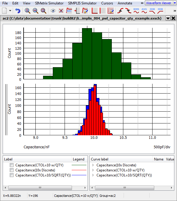
Monte Carlo Distributions With Quantity
- A single multi-level capacitor with QTY=10, and a 10% tolerance (Green histogram curve)
- 10 discrete capacitors with a 10% tolerance, wired in parallel (Red histogram curve)
- A single multi-level capacitor with a tolerance = ???MATH???\frac{\text{10%}}{\sqrt{\text{QTY}}}???MATH??? (Blue histogram curve)