SIMPLIS Discrete Time Filters
SIMPLIS includes a library of discrete time filters used for modeling digital control loops. These filters process analog control signals, producing outputs with the desired z-domain transfer functions. The discrete time filters are compatible with the POP and AC analyses, allowing direct simulation of digital control-loop behavior.
Devices in the library include:
- 1st Order Discrete Time Filter
- 2nd Order Discrete Time Filter
- PID Discrete Time Filter
- Sampler and Zero-Order Hold
- Sampling Clock Generator for Discrete Filters
- Track and Hold for Discrete Filters
- Unit Delay
Each of the discrete time filters is driven by an input clock signal.
- For proper operation, the input clock signal needs to be made up of a train of pulses with pulse widths equal to or wider than the Time of Acquisition set for the filter.
- For the most efficient simulation, the pulses can be generated by connecting a periodic pulse source, such as a waveform generator, to the input of a Sampling Clock Generator for Discrete Filters.
- The CLK_OUT output of that device will generate the input clock signals for the discrete filters. The driving periodic pulse source can have pulse widths shorter than the time of acquisition as long as they are well defined pulses.
A schematic of the connection between a Sampling Clock Generator for Discrete Filters and a 1st Order Discrete Time Filter is shown below. 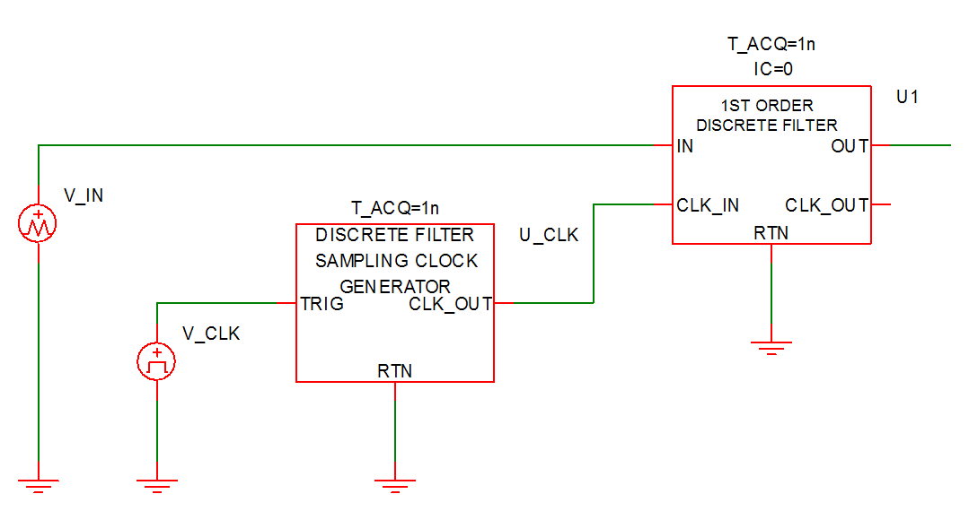
This example can be downloaded here: simplis_034_1stordfilter_example
- If the time of acquisition is tACQ, the Sampling Clock Generator for Discrete Filters generates a pulse width equal to tACQ every time that the TRIG input makes a positive transition exceeding 3V.
- During this pulse, the discrete filter samples the input data at the input pin IN. The time to satisfactorily acquire the input data is equal to tACQ.
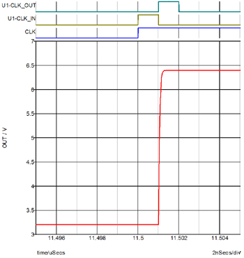
- After tACQ has expired, the discrete filter updates its output, and the output settles within a time duration less than or equal to tACQ.
- While the output is being updated, the output CLK_OUT is raised to a high value.
This timing behavior is described by the waveforms below:
A discrete filter with more than two poles can be synthesized through a cascade of one-pole
and/or two-pole discrete filters. In that case, the timing signal for each driven stage is
derived from the CLK_OUT signal of the immediately preceding stage. A schematic
using cascaded connections of a 1st Order Discrete Time Filter and a 2nd Order Discrete Time Filter is shown below.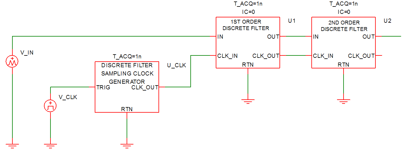
This example can be downloaded here: simplis_001_cascaded_filters_example