Multi-Tone AC Analysis Theory
Since the theory behind Multi-Tone analysis could fill volumes. this is a concise, engineering-specific, need-to-know guide to Multi-Tone AC analysis as it applies to testing power circuits using SIMetrix/SIMPLIS DVM. A deep mathematical discussion of Multi-Tone theory is left to the reader and to other sources.
In this topic:
Multi-Tone Injection Source
As with small signal analyses, an injection source is used to perturb the control loop. In a small signal analysis, this source is a single frequency or, in the termimology of this topic, a single tone. The small signal source is swept either linearly or more commonly, with a decade sweep. The circuit is perturbed one frequency at a time, and the calculation of the AC response due to this perturbation is straightforward to calculate.
In the Multi-Tone AC analysis, a large-signal source consisting of multiple time-domain sinusoidal voltages is used to perturb the control loop during a transient analysis. In circuit terms, these frequency sources are ideal sinusoidal voltage sources connected in series. Each frequency is harmonically related to the other frequencies and has an amplitude selected to perturb the loop with a known RMS amplitude. While the amplitude of each frequency is the same, the phase relationship between the frequencies is purposely selected to minimize the crest factor of the series-connected source. Crest factor in this context is the ratio of the peak to the RMS voltages of the source.
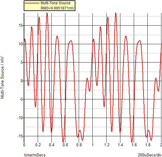
Pictured below is a Multi-Tone AC source with 10 harmonic frequencies ranging from 1kHz to 10kHz. The transient stop time is 2ms, yielding two full cycles of the lowest (fundamental) injected frequency. In this case, the source is programmed to have an RMS amplitude of 10mV.
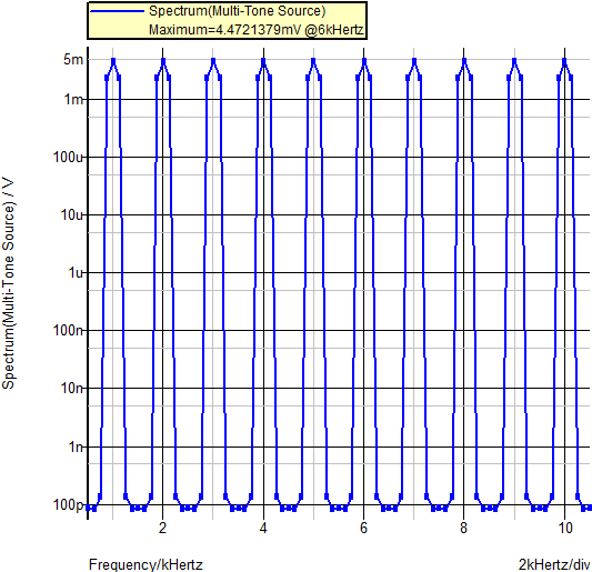
The frequency content of the source can be seen more easily on a spectrum plot of the source. In the plot below, the same source was simulated for 8 periodic cycles of the lowest injected frequency. The amplitude of the individual frequencies is 4.47mV, which is less than the overall 10mV RMS value of the source. The amplitudes of the injected frequencies add up in a predictable manner.
Steady-State Requirements
During a Multi-Tone AC analysis, Fourier techniques extract the AC response of the circuit under test from the transient simulation data. For the Fourier analysis to be valid and noise-free, the circuit under test must be completely settled into a periodic steady state. This requirement is easily met with the SIMPLIS POP simulation which forces the circuit to a very accurate steady-state operating point. In the Multi-Tone AC analysis, there is no "outer loop" which forces the circuit into a periodic steady state. You must make certain that the transient simulation has run long enough to allow the natural response of the circuit to completely die out.
DVM uses the FindAcSteadyState() Test Objective to determine the steady-state operating conditions of the circuit.
Harmonic Relationships
Because Fourier analysis is used to extract the AC response and the circuit is perturbed by a harmonic series of frequencies, you need to pay attention to the harmonic relations between various frequency sources present in the circuit. These harmonic relationships include the following:
- The relationship between the source harmonics
- The relationship between the simulation stop time and the lowest frequency present in the source
- The harmonic relationship between other large-signal periodic sources and the injection source in the circuit.
For example, if a PFC converter is simulated using Multi-Tone AC techniques, the fundamental injected frequency will likely be lower than the line frequency. You need to pay attention to the lowest injected frequency to ensure that the line frequency is a higher order harmonic of the lowest injected frequency and that an integer number of line cycles are simulated.
Parameters
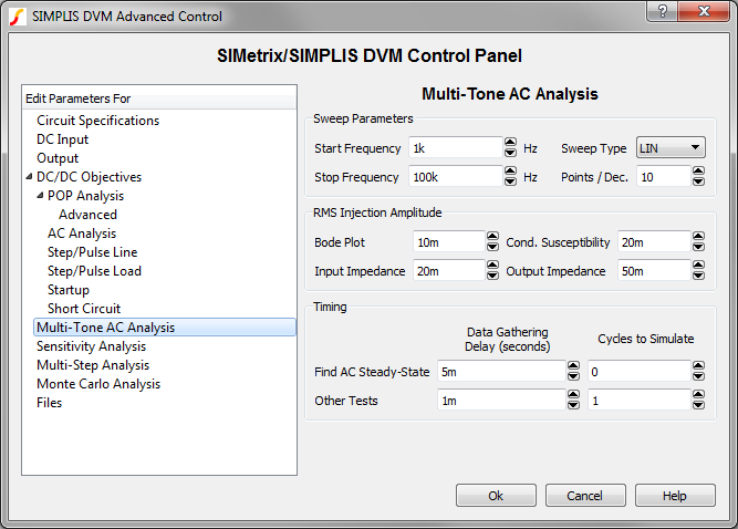
To setup a Multi-Tone AC source, five parameters are required:
- Start Frequency
- Stop Frequency
- Sweep Type
- Number of Points
- RMS Injection Amplitude
DVM automatically sets these parameters on the input source or output load during a Multi-Tone AC analysis. The values for these parameters are taken directly from the DVM control symbol from the dialog shown below:
Signal-to-Noise Ratio
Finally, the circuit which is operating under Multi-Tone injection is a very noisy environment. For the AC analysis to be of any use, the Fourier analysis must be able to selectively pick out each injected harmonic frequency and calculate the AC response at that point. A counter-intuitive effect is seen in the Multi-Tone AC analysis. Although you might think that more frequency points would yield a smoother frequency response curve, the exact opposite is true: as the number of injected frequencies is decreased, the signal-to-noise increases , yielding cleaner AC results at the expense of fewer data points. You should inject only the minimum number of points required to characterize the control loop.