SystemDesigner Bus Probe (SD Buses)
SystemDesigner Bus Probes plot the value of a SystemDesigner Bus in several ways. You can place the output curve on the digital or analog axis or on a grid and on separate graph tabs. Curves from multiple probes can be collected on one analog axis by specifying a common axis name. Likewise, curves can be output to the same graph by specifying a common graph name.
In this topic:
| Model Name: | SystemDesigner Bus Probe | |
| Simulator: |
|
This device is compatible with the SIMPLIS simulator. |
| Parts Selector Menu Location: |
SystemDesigner Functions (max. 32 bit ) | Probes | |
| Symbol Library: | SIMPLIS_SystemDesigner_Probes.sxslb | |
| Model File: | None - Electrically inactive | |
| Subcircuit Name: | None - Electrically inactive | |
| Symbol: |
|
|
| Multiple Selections: | Multiple SystemDesigner Bus Probes may be edited at a time. When multiple probes are selected, the Curve label box is disabled, preventing multiple probes from having the same curve label. | |
Editing a SystemDesigner Bus Probe
To edit a SystemDesigner Bus Probe, double click the symbol on the schematic.
The
Edit SystemDesigner Probe dialog appears.
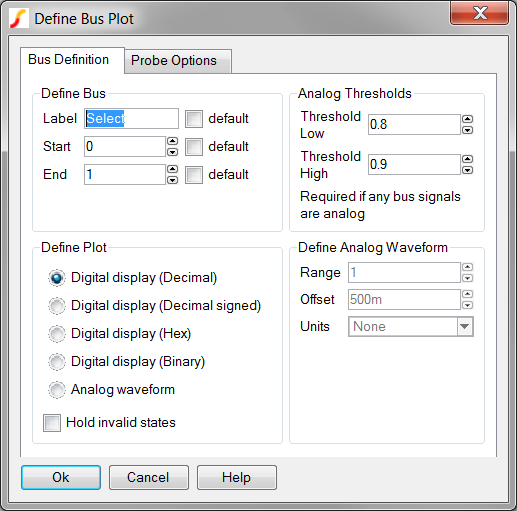
| Label | Parameter Description | ||||||||||
| Curve label | The name of the curve on the graph viewer. This name may contain spaces and any special character except double quote. | ||||||||||
| Plot Integer data as: |
|
||||||||||
| Axis type for analog waveform |
The analog waveform may be output in several locations:
|
||||||||||
| Gain | The curve
amplitude is multiplied by this value before plotting. Setting a gain for a SystemDesigner bus is helpful to see how the bus value maps to the actual analog value of the sampled signal. |
||||||||||
| Axis name | The name
for the new axis or grid. Specify an axis name for each new axis and
grid. Curves with the same axis name are output to the same axis or grid. |
||||||||||
| Display order | Alphanumeric sort order for the curves. Curves on a common axis appear
in alphanumeric order from top-to-bottom on the axis. |
||||||||||
| Persistence | Persistence
sets how long curves remain on the graph.
|
||||||||||
| Graph | Curves
without a specified Graph name are output to the default graph
tab. Probes with the same Graph name are output to a new graph tab. Any number of new graph tabs may be defined by specifying different graph names. |
||||||||||
| Analyses |
|
||||||||||
| Colour | If checked, the program selects a color from a sequence of built-in colours. You may select any colour by clicking on the Edit button. |
Examples
The SystemDesigner Bus Probe is used in multiple examples in this help project. Below are links to some of the topics with bus-probe examples: