5.2.2 Adding Tabbed Parameter-Editing Dialogs
To download the examples for Module 5, click Module_5_Examples.zip.
In this topic:
Key Concepts
This topic addresses the following key concepts:
- Tabbed parameter-editing dialogs allow you to create more precise dialogs at the expense of requiring more data and more development time.
- The dialog definitions for the NewValueDialog and TabValueDialog are not interchangeable.
- Three additional parameter types in the TabValueDialog are allowed: GROUP, GROUPCHECK, and LABEL.
- The TABS symbol property holds the tab names for the dialog definition.
- The GROUPS symbol property holds the group box definitions for the dialog.
- The dialog title and dialog box caption are stored in the DESCRIPTIONS symbol property.
- A spreadsheet software tool is almost mandatory to define tabbed dialogs.
What You Will Learn
In this topic, you will learn the following:
- How the tabbed parameter-editing dialogs work as an extension of the basic parameter-editing dialogs
- The differences between the NewValueDialog and TabValueDialog dialog definitions that prevent them from being interchanged
- How to work with three additional parameter types: GROUP, GROUPCHECK, and LABEL
- How to specify the tab names in the TABS symbol property
- How to specify the group box definitions in the GROUPS symbol property
- How to specify the dialog title and caption in the DESCRIPTIONS symbol property
- Why a spreadsheet software tool is almost mandatory for defining tabbed dialogs
Introduction
In 5.2.1 Adding Basic Parameter-Editing Dialogs, you learned how to add basic dialog definitions. For many applications, the basic dialog is perfectly acceptable; however, when editing a large number of parameters, it is helpful to collect related parameters into a group box and then separate the group boxes on tabs. The resulting dialog is smaller, and the user is less likely to be overwhelmed by the number of controls presented at one time.
In this topic, you will learn the benefits of using the TabValueDialog to create parameter-editing dialogs.
Hierarchy of a Tabbed Dialog
The following dialog serves as an example to illustrate the hierarchy within a tabbed
dialog. 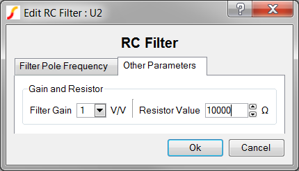
- At the top level of the hierarchy are two tabs: Filter Pole Frequency and
Other Parameters.
- In the second level of the hierarchy on the Other Parameters tab is the group
box Gain and Resistor. Although a tab can have multiple group boxes,
this example has just one.
- On the third level of hierarchy are the parameter-editing controls Filter Gain and Resistor Value.
- In the second level of the hierarchy on the Other Parameters tab is the group
box Gain and Resistor. Although a tab can have multiple group boxes,
this example has just one.
This hierarchical structure allows you to easily build custom dialog boxes to edit your model parameters; however, certain rules are absolute:
- You cannot place a parameter-editing control on a tab without placing it inside a group box.
- Group boxes are placed on a grid on each tab.
- Each parameter-editing control is made up of the descriptive label, the editing control, and an optional units label.
- Parameter-editing controls are placed on a grid inside a group box.
Required Data Elements
This dialog example requires far more information to generate the definition than the basic dialogs described in 5.2.1 Adding Basic Parameter-Editing Dialogs. The three additional data elements are described below:
Tabs
The TabValueDialog function constructs a map of available tabs based on the tab titles you provide. Tabs are created in left-to-right order from the comma separated list of tabs definitions. In this dialog example, the TABS symbol property value has two elements separated by a comma as shown below:
Filter Pole Frequency,Other Parameters
Groups
The groups definition for any single group box is made up of 10 data fields described in the following table.
| Data Field | Example Data Value | Description |
| Parent Tab | Other Parameters | The tab defined in the Tabs section on which to create the group box. |
| Group Type | GROUP |
|
| Group Title | Gain and Resistor | Title for the group |
| Starting Row | 0 | The starting row on the tab grid pattern. 0 is the first row |
| Starting Column | 0 | The starting column on the tab grid pattern. 0 is the first column |
| Ending Row | 0 |
The ending row on the tab grid pattern. Note: If
you make this number larger than the starting row, the group box spans
multiple rows.
|
| Ending Column | 0 |
The ending column on the tab grid pattern Note: If
you make this number larger than the starting column, the group box
spans multiple columns.
|
| Control Idx | 0 | The CHECK group type is
considered a Boolean parameter, which returns a value of 0 or 1; however,
to use a checkable group you must tell the program which parameter in the
parameter string, PARAMETERS, is assigned the returned value of Checked
(1) or not Checked (0). The Control Idx data element identifies which parameter should be assigned the checkable group box Boolean value. The first parameter in the PARAMETERS string is at index 0. To use the checkable group box, first assign the parameter-editing controls including a parameter name for the checkable group box. Then, assign the index of this parameter in the PARAMETERS string to the Control Idx for the Group definition. The Control Idx is ignored for the GROUP type. |
| Add Vertical Lines | 1 | Adds a vertical separation line between multiple columns of parameter-editing controls in a single group box. Does nothing if the group has a single column of parameter-editing controls. |
| Column Spacing | 0 | A positive integer to indicate the number of pixels between columns. 0 specifies the default, which is 6 pixels. |
As with the basic dialog definition, each group data element is concatenated with the colon character to produce a group definition string:
Other Parameters:GROUP:Gain and Resistor:0:0:0:0:0:1:0
Multiple group definitions are further concatenated with the comma character. This dialog example has two groups. The complete definition for both groups used in this dialog is as follows:
Filter Pole Frequency:GROUP:Filter Parameters:0:0:0:0:0:0:0,Other Parameters:GROUP:Gain and Resistor:0:0:0:0:0:1:0
The order of the individual group definitions doesn't matter. After concatenating this text string the group information is stored on the symbol property GROUPS.
Descriptions
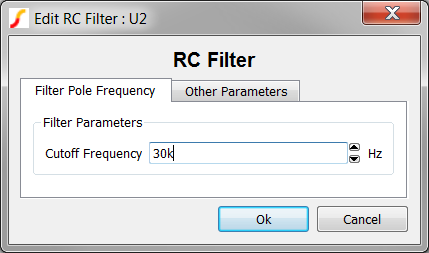
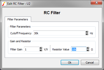
The tabbed dialog provides a bold dialog title and a dialog caption. These two data elements are stored in a comma separated list on the DESCRIPTIONS symbol property. For this dialog, the dialog title is RC Filter, and the caption is Edit RC Filter. Notice in the dialog image, the caption is actually Edit RC Filter : U2. The colon and the reference designator are added by the valuescript when the user double clicks on the symbol. The title can contain html formatting or escape characters. The complete DESCRIPTIONS definition for this dialog is as follows:
Edit RC Filter,RC Filter
Parameter-Editing Control Data Fields
Each parameter-editing control for the basic parameter-editing dialog has three data elements. For the tabbed value dialog, considerably more information is required, and there are 10 fields for each parameter-editing control as described in the following table.
| Data Field | Example Data Value | Description | ||||||||||||||||||
| Parent Tab | Other Parameters | The tab containing the group box and the parameter-editing control | ||||||||||||||||||
| Parent Group | Gain and Resistor | The group on the Parent Tab in which to place this parameter editing control | ||||||||||||||||||
| Descriptive Label | Filter Gain | Any text string with html formatting or escape characters. | ||||||||||||||||||
| Row | 0 | The row on the grid inside the group box to place this control. 0 is the first row | ||||||||||||||||||
| Column | 0 | The column on the grid inside the group box to place this control. 0 is the first column | ||||||||||||||||||
| Units | V/V | Any text string with html formatting or escape characters. Can contain the
following special keywords, which are case
sensitive!:
|
||||||||||||||||||
| Type | LIST | Eight types of
parameter-editing controls are allowed with the TabValueDialog function.
The most common types are the Real and Integer spinner controls, followed
by the List and Boolean types. The String entry type can be used to
prompt the user for general string information and is used infrequently.
The eight types are
described in the table below:
|
||||||||||||||||||
| Range | 1|2|5|10 | For REAL and INTEGER types,
the minimum and maximum values separated by a pipe "|" character.
Engineering suffixes are permitted.
For the LIST (used in this example) control type, the range is a pipe separated list of allowed values. The available options in the list box are populated from top to bottom with the range data in left-to-right order. |
||||||||||||||||||
| Flags | 0 |
Four types can have an associated flag:
For all other data types, the value is ignored. |
||||||||||||||||||
| Tool Tip | The Gain of the Filter | The tool tip can be any string with html formatting or escape characters. The tool tip appears in a box with a yellow background when the user hovers the mouse over the control or the descriptive label for that control. |
As with the basic dialog definition, the data elements are concatenated with the colon character into a parameter-editing control definition. The single parameter-editing control definition for the Filter Gain control is as follows:
Other Parameters:Gain and Resistor:Filter Gain:1:0:V/V:LIST:1|2|5|10:0:The Gain of the Filter
Multiple parameter-editing control definitions are further concatenated with the comma character. This dialog example has three parameters and the complete definition for all parameters is as follows:
Filter Pole Frequency:Filter Parameters:Cutoff Frequency:0:0:Hz:REAL:1p|100G:1:The Filter Pole Frequency in Hertz,Other Parameters:Gain and Resistor:Resistor Value:0:1:__Ohms__:INT:1|100k:1:The resistor value used in the R-C filter in Ohms,Other Parameters:Gain and Resistor:Filter Gain:0:0:V/V:LIST:1|2|5|10:0:The Gain of the Filter in V/V
As with the basic parameter-editing dialog, the order of the parameter editing control definitions must be the same as the parameters in the PARAMETERS symbol property. After concatenating the parameter-editing control definitions, the resulting string is stored on the LABELS symbol property.
The VALUESCRIPT Symbol Property
The VALUESCRIPT symbol property holds the script name to execute when a user double clicks on the symbol. The tabbed parameter editing dialogs are only available for symbols which use the Multi-Property Method. The valuescript is:
edit_parameterised_multi_prop_device_tab_value_dialog 1
This valuescript takes a single argument - in this case 1. The argument determines if the reference designator is appended to the caption defined in the Descriptions. If the argument is 1, the reference designator is appended, if the argument is 0, the caption defined in the DESCRIPTIONS symbol property is used.
You Really Need a Tool for This
By now you should see the benefit of a tabbed dialog, especially for a large number of parameters. However, the complexity of this dialog definition can be overwhelming. As with the basic dialogs, a spreadsheet can help ease the design process.
Exercise #1: The TabValueDialog Spreadsheet
This exercise walks you through the structure of the spreadsheet to help you understand the process.
- Open the spreadsheet 5.4_tab_value_dialog_definition_worksheet.xlsx located in the C:\Training\Module_5_Examples directory.
- Notice that the spreadsheet is broken down into 5 numbered steps:
- Step #1 defines the type of dialog: Tabbed or Radio Select
- Step #2 defines the tabs
- Step #3 defines the groups
- Step #4defines the labels
- Step #5 defines the descriptions
- Notice that the same formatting is used as with the basic dialogs:
- User inputs are formatted as follows:
- Calculated cells are shown with this format:

- User inputs are formatted as follows:
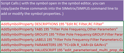
- Six script commands are concatenated in cells B43~B48. When executed in SIMetrix/SIMPLIS, these commands add (or change) the symbol properties to the symbol that is currently open in the Symbol Editor.
In the next exercise you will add the tabbed parameter-editing dialog to the parameterized RC filter symbol.
Exercise #2: Add Parameter-Editing Dialog
As with the Basic Add Parameter-Editing Dialog Exercise, you will copy a set of script commands from the spreadsheet and execute the commands in SIMetrix/SIMPLIS.
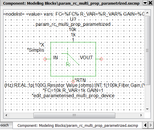
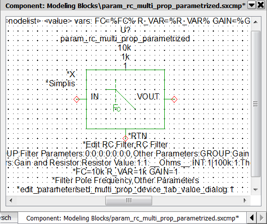
- Open the schematic 5.5_parametrized_rc_filters_multi_prop_dialogs.sxsch . This example is pre-prepared with the Multi-Property parameterization method. The only part missing is the parameter editing dialog.
- To add the parameter-editing control definitions to the symbol for the
parameterized RC filter, follow these steps:
- On the SIMetrix/SIMPLIS schematic, select the symbol for U2.
- To open the schematic component in the Symbol Editor, type the keyboard
shortcut Shift+S, or right click and select Edit Symbol....
Result: The symbol opens in the Symbol Editor with the NewValueDialog definition properties.
- Navigate to the spreadsheet window, and select the red text in cells
B43~B48.Result: The selected cells should appear as follows:
- Press Ctrl+C to copy the cells to the windows clipboard. Result: The selected cells have an animated border indicating the cells are selected.
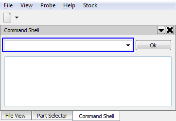
- Navigate to the SIMetrix/SIMPLIS command shell window.
- Click the mouse in the command line entry located at the top of the command
shell window:
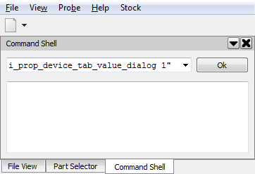
- Press Ctrl+V to paste the commands in the command line. Result: The last part of the command string is visible in the command line:
- Press Enter, or click Ok on the command line. Result: The commands are executed in SIMetrix/SIMPLIS. Each AddSymbolProperty command adds a single symbol property to the symbol. Each ChangeSymbolProperty modifies the existing property. The commands apply the Hidden and Protected property flags and add the parameters below the symbol.Note: This step overwrites the previous NewValueDialog definition.
- Press Ctrl+S to save the symbol, and then click Ok on the Save Symbol dialog.
- Navigate to the Schematic Editor window. Double click on U2, which is the
RC filter attached to the multi-prop(30kHz) probe. Result: The parameter-editing dialog opens:
- Select the Other Parameters tab and change the Resistor Value to 10k.
- Click Ok to save your changes. Result: The parameter value for R_VAR changes to 10000 on the schematic.Note: The parameter-editing control for the resistor value is currently an integer type control, which returns numbers in non-engineering notation.
Exercise #3: Modify The Dialog Definition
In the previous exercise, you added a parameter-editing definition saved in the spreadsheet. This definition used three control types as a demonstration; however, the parameters being edited should be REAL types. In this exercise you will modify the dialog definition to use the REAL type control for all parameters. You will also move the three filter parameters onto one tab but inside two group boxes.
- Navigate to the spreadsheet window.
- To delete the Other Parameters tab, select cell B14.
- Right click to bring up the context menu and select Delete > Table
Rows:
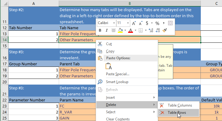 Result: Row 14 defining the Other Parameters tab is removed from the tabs table.Note: Whenever you add or remove tabs, groups, or parameter editing controls, you must add or delete rows from the excel tables.
 - To rename the single remaining tab, change the text in cell B13 from
Filter Pole Frequency to Filter Parameters.Note: You will now need to redefine all groups and parameters, as the groups and parameters use tabs which no longer exist.
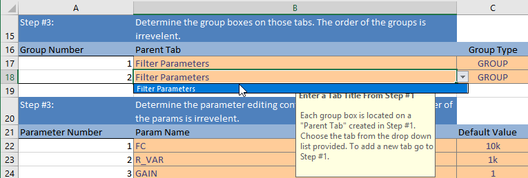
- To move both group boxes to the new Filter Parameters tab, select Filter
Parameters from the drop-down menu in cells B17 and B18.
- To move the Gain and Resistor group below the Filter Parameters group
box, change cells G18 and I18 to 1. Result: This will move the Gain and Resistor group box to the second row on the Filter Parameters tab, below the existing Filter Parameters group defined on row 17.
- To move each parameter editing control to the group boxes on the Filter Parameters tab, select Filter Parameters from the drop-down menu in cells J22, J23, andJ24.
- To change the parameter editing control to real-valued spinners, change the content of cells H23 and H24 to REAL.
- Delete the contents of cell I24, which is the range entry for the Gain
parameter. Result: Without a range entry, any gain, including negative gain, can be entered in the parameter-editing control.
- Copy the commands in cells B42~B47, and paste the commands into the SIMetrix/SIMPLIS command line.
- Press enter or click Ok on the command line.
- Press Ctrl+S to save the symbol, and then click Ok on the Save Symbol dialog.
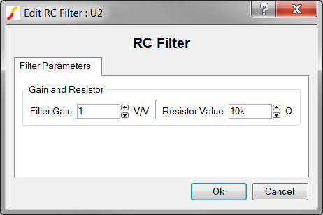
- Double click on the RC Filter symbol. Result: The modified dialog opens. Each control type is a Real type, and the controls are all on one tab.
- Click Ok. Result: On the schematic, the value of the Resistor Value parameter R_VAR changes from 10000 to 10k. The REAL type parameter editing control returns values formatted in engineering notation.
Escaping the Concatenation Characters
'Note: some text, with a comma'or you could use the escape character
'Note\: some text\, with a comma'
Using HTML in Labels
<strong>bolded text</strong>
<i>italicized text</i>
<u>underlined text</u>
Adding Images to a TabValueDialog
Along with formatting the text, HTML allows you to add images to your dialogs. There are two ways of placing images into your dialogs, both of wich use the HTML <img> tag.
<img src="./images/image_to_add.png">This method would require all of the necessary images to be packaged with the schematic for distribution, and for these images to be located at the correct relative paths.
The relative path issue will be problematic when working with a design which uses multiple hierarchical levels. Each image has to be present in the directory where the schematic component is used, as opposed to in the directory where the schematic component is saved. For these reasons, there is a more robust method which is free of the relative path issue.
<img src="data:image/png;base64,base64_encoded_content">and the following format for bmp formatted images:
<img src="data:image/bmp;base64,base64_encoded_content">
Show /plain /clipboard EncodeImageToBase64()
Once the string has been copied to the clipboard, you can paste it into the dialog definition worksheet using the image tags listed earlier. The image, in it's base64 form, is now a part of the symbol itself, and there are no additional files to handle and no relative path issues.
What Can Go Wrong?
In addition to the common problems described in 5.2.1, What Can Go Wrong?, the tabbed value dialog has these additional common problems.
- Typing and spelling errors. Seemingly minor typographical errors as well as
any spelling mismatches will have significant consequences.
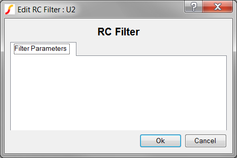
- An extra space character: If the Parent Tab for Exercise #3 contains an
extra space after the "s" in Parameters, the dialog will have only a tab with
no group boxes and no parameter controls as shown below: Note: Observe the extra space that appears inside the dotted outline around Filter Parameters.
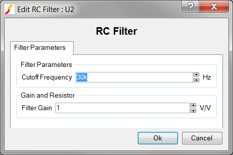
- An extra letter: When a group title does not match the parameter
controls, such as adding an "s" to the group name as shown below for Gain
and Resistor, the group will be empty because no control matches the
Parent Tab and Parent Group:
-
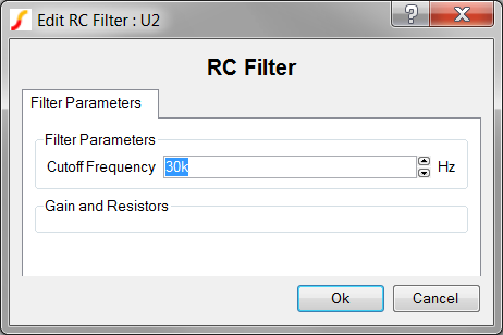
Mismatched spelling of a Parent Group or Parent Tab for a parameter
control: When the parameter-editing control value for the Parent Tab or
Parent Group does not exactly match the spelling of the actual name of the
group or tab, that parameter control is not constructed. For example, if
Gain and Resistors was defined as the parent group for Resistor
Value when it should have been Gain and Resistor, that control
will not appear as illustrated in the dialog below.
- An extra space character: If the Parent Tab for Exercise #3 contains an
extra space after the "s" in Parameters, the dialog will have only a tab with
no group boxes and no parameter controls as shown below:
-
Over-writing groups or parameter controls. Groups are created on each tab in a
grid pattern. If you specify the same grid location for more than one group box, the
second group box will be created on top of the previous group box. Both the Filter
Parameters and Gain and Resistor groups were created at Start Row = End Row = Start
Column = Stop Column = 0. A similar problem occurs when multiple
parameter-editing controls are placed at the same row and column in a single group
box.
Conclusions and Key Points to Remember
- Tabbed parameter-editing dialogs allow you to create more precise dialogs at the expense of requiring more data and more development time.
- The dialog definitions for the NewValueDialog and TabValueDialog are not interchangeable.
- Three additional parameter types in the TabValueDialog are allowed: GROUP, GROUPCHECK, and LABEL.
- The TABS symbol property holds the tab names for the dialog definition.
- The GROUPS symbol property holds the group box definitions for the dialog.
- The dialog title and dialog box caption are stored in the DESCRIPTIONS symbol property.
- A spreadsheet software tool is almost mandatory to define tabbed dialogs.