Digital Signal Source
The Digital Signal Source provides a flexible way to define a digital circuit stimulus. The digital signal source can have between 1 and 32 output pins. For simple signals, you can use a parameter editing dialog. For complex signal definitions, you can use a simple tab separated ASCII text file.
For single bit periodic sources, such as clocks, see Digital Pulse Source.
In this topic:
| Model Name: | Digital Signal Source | |||
| Simulator: | This device is compatible with the SIMPLIS simulator. | |||
| Parts Selector Menu Location: | ||||
| Symbol Library: | None - the symbol is automatically generated when placed or edited. | |||
| Model Library: | None - the model is automatically generated when the simulation is run. | |||
| Subcircuit Names: |
|
|||
| Symbol: |
|
|||
| Multiple Selections: | Only one device at a time can be edited. | |||

Editing the Digital Signal Source
To configure the Digital Signal Source, follow these steps:
- Double click the symbol on the schematic to open the editing dialog to the Parameters tab.
- Make the appropriate changes to the fields described in the table below the image.
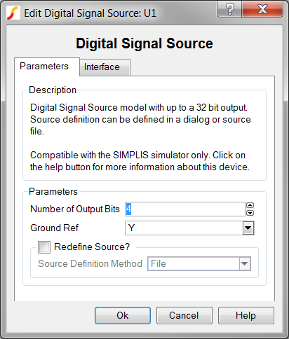
| Label | Parameter Description |
| Number of Output Bits | Number of source output bits, minimum of 1, maximum of 32. |
| Ground Ref | Determines whether or not a device has a ground reference pin. Any digital component that has an input or output pin connected to an analog circuit node must have its Ground Ref pin connected to an analog node. This is usually the ground on the schematic. |
| Redefine Source? | Determines whether the
source is to be redefined after the dialog is closed.
|
To define the parameters for the interface between this digital component and each analog component connected directly to an input or output pin, follow these steps:
- From the Edit Digital Signal Source dialog box, click on the Interface tab.
- Make the appropriate changes to the fields described in the table below the image.
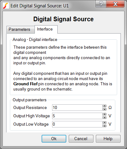
| Label | Parameter Description |
| Output Resistance | Output resistance of each output pin. |
| Output High Voltage | Output high voltage of each output pin. |
| Output Low Voltage | Output low voltage of each output pin. |
Table Definition Methods
The Digital Signal Source can be defined with a dialog, or with a points file.
Dialog Method
Using the dialog method, the points definition is saved to a property on the Digital Signal Source symbol. This method is often used for small source definitions. You can define up to 255 logical input states with the dialog method.
To define the source with this method, follow these steps:
- On the Parameters tab of the Edit Digital Signal Source dialog box, check Redefine Source?.
- Select dialog in the Source Definition Method box.
- Click Ok.Result: The main dialog closes, and a table editing dialog will open.
File Method
With the file method, the points definition is saved as a plain ASCII text file. Before the simulation starts, the points file is read and used to configure the source. This method is often used for large or complicated source definitions, although you can use this method for any size table.
The source used in the SIMPLIS Lookup Table with Don't Care Input Definitions example demonstrates the file format.
- The file method uses whitespace, including tabs and spaces to delimit columns in the points definition file.
- Lines starting with the asterisk (*) are considered comments and are ignored.
- The Time is defined in the first column.
- The states for each output pin follow in MSB -> LSB order. Since these are single bits, the output states are defined as either 0 or 1.
- Any number of points can be defined using the file method.
The following example has five columns, one for the time and four for the output
bits. 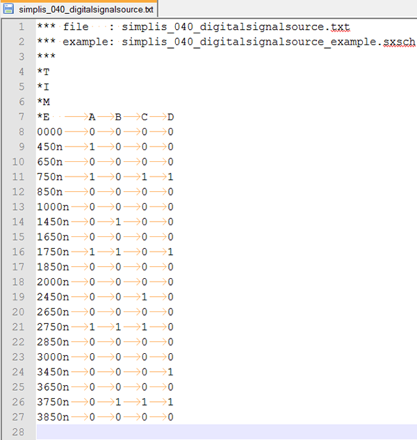
An example points definition file can be downloaded here: simplis_040_digitalsignalsource.txt. This file is also included in the zip archive of the example files (simplis_040_digitalsignalsource_example.zip).
Common File Formatting Issues
The file definitions for the Digital Signal Source and the Digital Lookup Tables are read into SIMPLIS by the same block of code. The errors in input file syntax are therefore similar. A description of the most common errors in input file formatting can be found here: Common File Formatting Issues
Examples
The test circuit used to generate the waveform examples in the next section can be downloaded here: simplis_040_digitalsignalsource_example.zip.
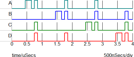
Waveforms
The waveforms below were taken from the state machine example described in the SIMPLIS Lookup Table with Don't Care Input Definitions.
Subcircuit Parameters
Because the Digital Signal Source model is generated by a template script when the simulation is executed, a hand-coded model cannot be inserted into a netlist. The template script for this device is simplis_make_signal_source_model.sxscr, which licensed users can download as part of a zip archive of all built-in scripts.
To download the zip archive, follow these steps:
- Click http://www.simetrix.co.uk/simetrix80/scripts.zip to download the script archive.
- Enter the user name and password you received with your license file.
The following parameter table defines the parameters used in this model.
| Parameter Name | Label | Data Type | Range | Units | Parameter Description |
| GNDREF | Ground Ref | String |
|
none | Determines whether or not a device has a ground reference pin. Any digital component that has an input or output pin connected to an analog circuit node must have its Ground Ref pin connected to an analog node. This is usually the ground on the schematic. |
| NUMBITS | Number of Output Bits | Integer | none | Number of source output bits, minimum of 1, maximum of 32. | |
| REDEFINE_SOURCE | Redefine Source? | Boolean | none | Determines whether the source
is to be redefined after the dialog is closed.
|
|
| ROUT | Output Resistance | Number | min: 1m | Ω | Output resistance of each output pin. |
| SOURCE_DEF | Source Definition Method | String |
|
none | Determines whether the definition of the digital signal source comes from a dialog or an external file. If Redefine Source? is checked, you will be prompted to edit the digital signal source definition with a dialog or to choose a new definition file, depending on the value of Source Definition Method after this dialog is closed. |
| VOH | Output High Voltage | Number | any | V | Output high voltage of each output pin. |
| VOL | Output Low Voltage | Number | any | V | Output low voltage of each output pin. |